

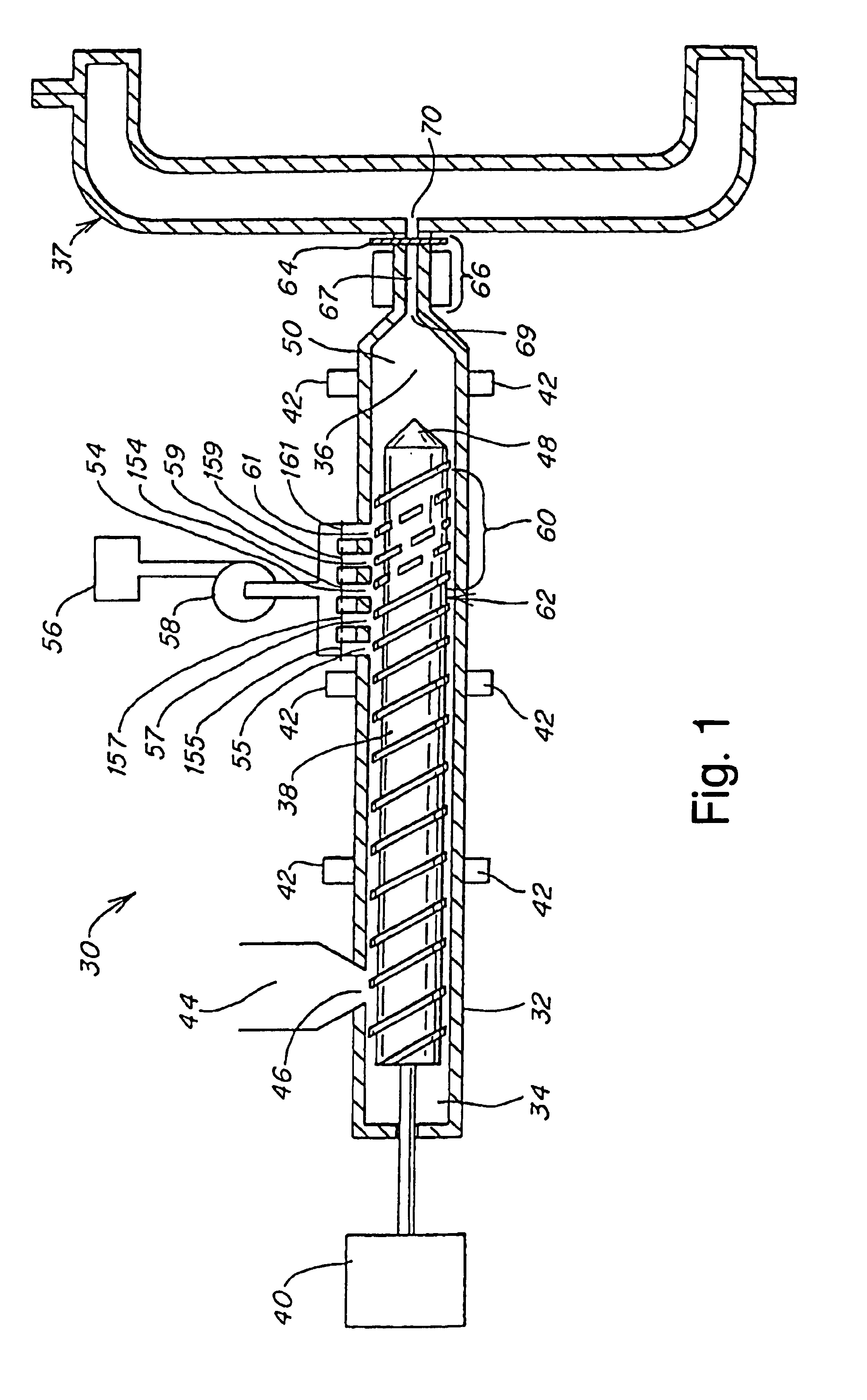
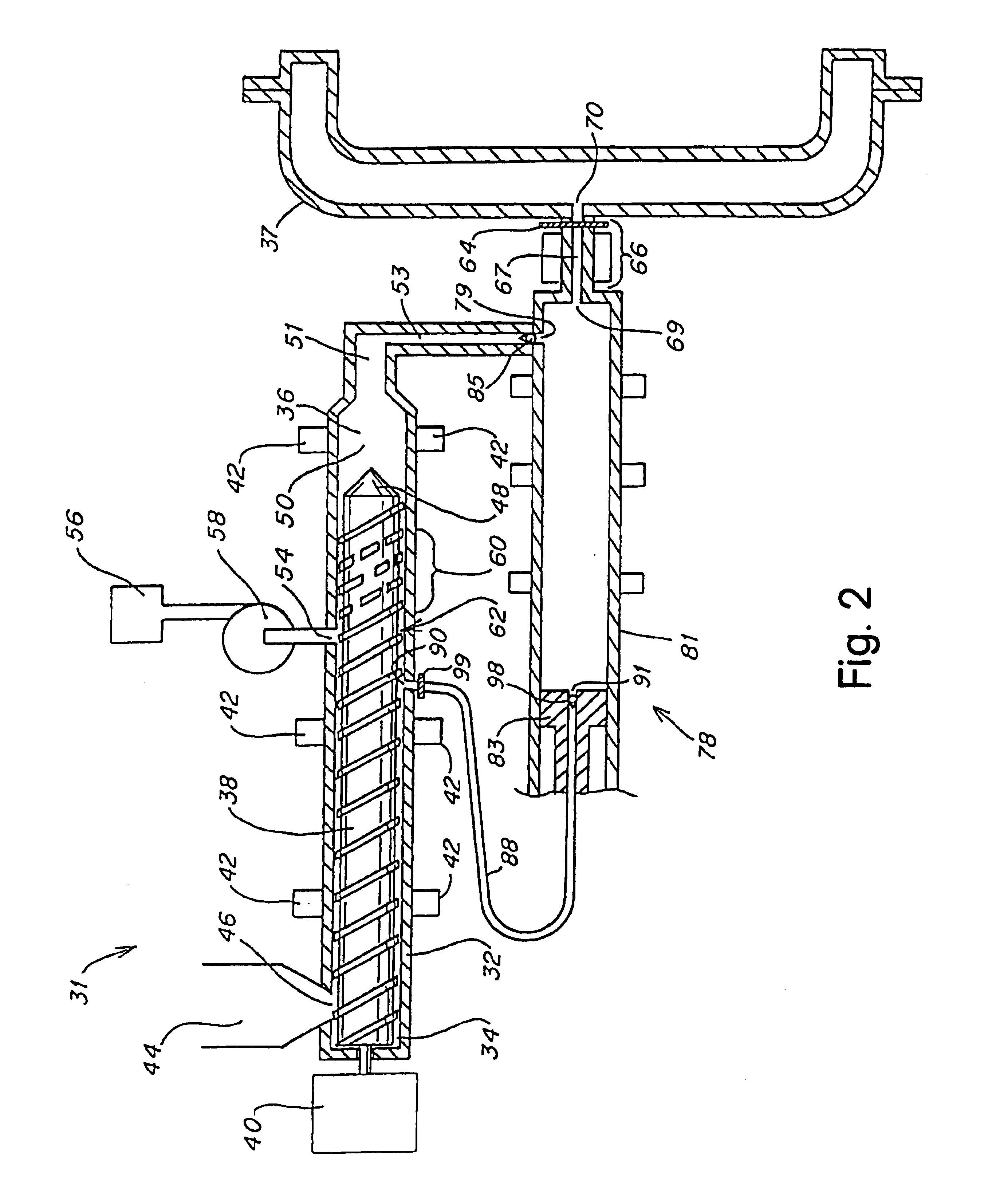
Injection molding of polymeric material
a polymer material and injection molding technology, applied in the direction of transportation and packaging, other domestic articles, flat articles, etc., can solve problems such as less than ideal appearan
- Summary
- Abstract
- Description
- Claims
- Application Information
AI Technical Summary
Benefits of technology
Problems solved by technology
Method used
Image

Examples
example 1
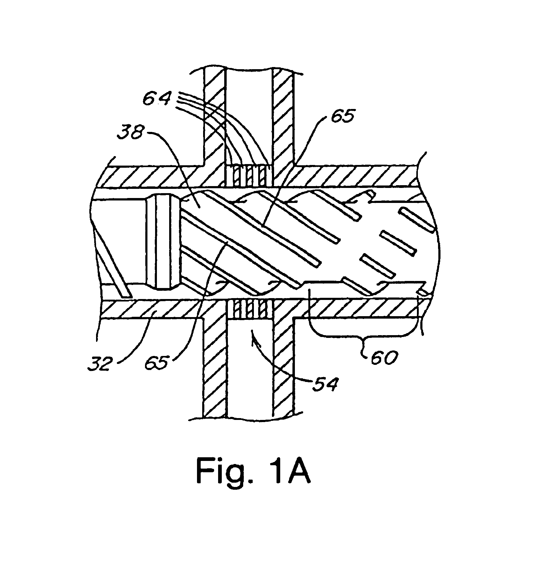
[0169]A two stage injection molder (Engel manufacture) was constructed with a 32:1 l / d, 40 mm plasticizing unit which feeds melted polymer into a 40 mm diameter plunger. The plunger and plasticizing units were connected by a spring loaded ball check joiner assembly. The plunger was able to inject into a mold through a typical pneumatically driven shut-off nozzle. Injection of supercritical CO2 was accomplished by placing at approximately 16 to 20 diameters from the feed section an injection system that included one radially positioned port containing 176 orifices of 0.02 inch diameter. The injection system included an actuated control valve to meter a mass flow rate of blowing agent at rates from 0.2 to 12 lbs / hr.
[0170]The plasticator was equipped with a two stage screw including a conventional first stage feed, barrier, transition, and metering section, followed by a multi-flighted mixing section for blowing agent homogenization. The barrel was fitted with heating / cooling bands. Th...
example 2
Injection Molding Microcellular Polystyrene
[0172]The molding machine as described in example 1 was used to mold microcellular polystyrene plaques. Polystyrene pellets (Novacor 2282, 11 M.I.) were fed into the plasticator and, in most cases, mixed with blowing agent to form a single-phase solution, then nucleated by injection into a 5×11×0.050 inch, center gated plaque mold. Injection occurred through a cold sprue. Injection rate was varied to determine the relationship between the processing variables and cell size and weight reduction. Cell size was controlled to under 30 microns and weight reduction as high as 20%. See Tables 1 and 2 and corresponding FIGS. 10-15.
[0173]
TABLE 1Effect of Injection Speed on Cell Size and Weight ReductionInjectionBlowingWeightSpeedCell SizeAgentReduction(“ / sec)(microns)(%)(%)FIG.11 No Cells11.911105100 11.9111141011.9191221011.9181313011.912—
[0174]
TABLE 2Effect of Gas Concentration on Cell Size and Weight ReductionMelt temperature = 160° C.Mold Temper...
example 3
Injection Molding Microcellular Polyethylene Terephthalate
[0175]The injection molding machine described in example 1 was used to mold PET (Eastman, 0.95 IV) into a 5×11×0.200 inch cavity after drying for four hours at 350 F. The melt processing temperature was 550 F, the mold temperature was 151 F and was injected with 12% CO2. The melt pressurization pressure was maintained at 3000 psi and the injection speed was 5.0 inches per second.
[0176]The weight reduction was 30% and the cell size was 30 to 40 microns in diameter.
PUM
| Property | Measurement | Unit |
|---|---|---|
| Length | aaaaa | aaaaa |
| Length | aaaaa | aaaaa |
| Length | aaaaa | aaaaa |
Abstract
Description
Claims
Application Information