Fork level indicator for lift trucks

Inactive Publication Date: 2001-06-12
CROWN EQUIP CORP
View PDF18 Cites 74 Cited by
  • Summary
  • Abstract
  • Description
  • Claims
  • Application Information

AI Technical Summary

Benefits of technology

This invention also includes a camera, which is equipped with a horizontal plane reticle and mounted on a vertically movable carriage assembly and which is protected from damage and contact with the floor when the forks are in their lowermost position. The camera is lowered to a first predetermined position below the forks and load when the forks are raised, which provides the camera with a view that is optimum for viewing a target for vertical height position of the forks or load. When used on a double reach truck with the forks extended, the camera is placed at a second predetermined location relative to the forks, which is above the first predetermined position and which provides the camera with a view above the load support beam or rail of a rack near which the truck is usually placed when operating in this mode. A second camera at a different height may also be used and switching means provided to allow the operator to obtain a view above the load support beam.
A video monitor is provided for use by the operator which, in addition to providing a horizontal plane reticle and a picture of the view observed by the camera, also provides a fork level indicator, and an indicator showing the truck functions selected by the operator. As used herein, the reticle includes a single horizontal line extending across the face of the monitor and a single vertical line at the center of view. This unique presentation aids the operator in controlling the operation of the truck, including the vertical, horizontal and level position of the forks, by reference to that monitor.
It is therefore an object of this invention to provide a le

Problems solved by technology

With a load on the forks, the best position for the camera is below the bottom of the load for use in operator viewing under-clearance or viewing alignment with a target below the load; however, in this position, the camera is subject to damage when the forks are lowered near the floor on which the truck is operating.
If the camera is fixed positioned to be clear of the floor when the forks are fully lowered, then its view will be too high to be effective for viewing belo

Method used


Image

  • Fork level indicator for lift trucks
  • Fork level indicator for lift trucks
  • Fork level indicator for lift trucks

Examples


Embodiment Construction

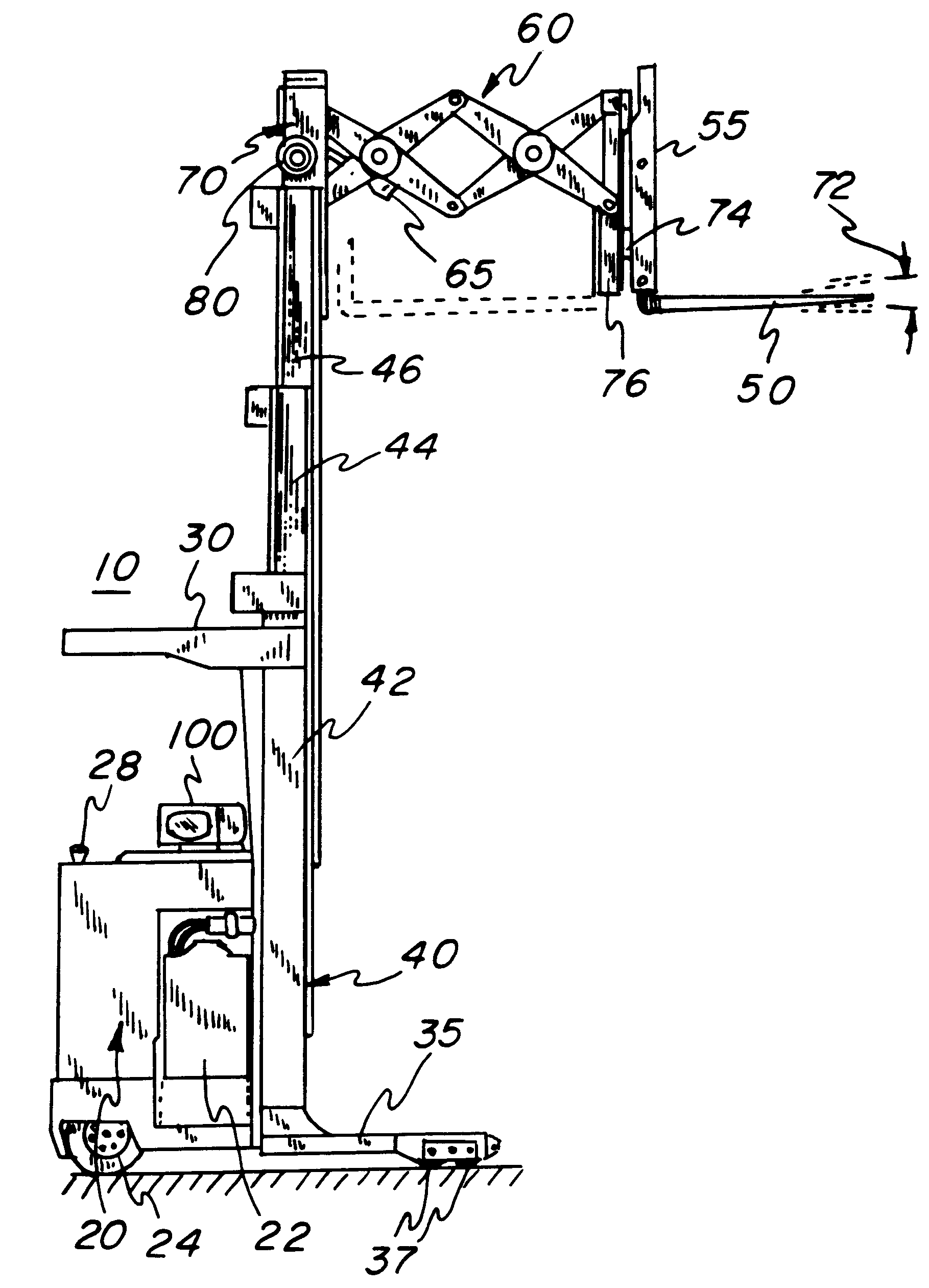
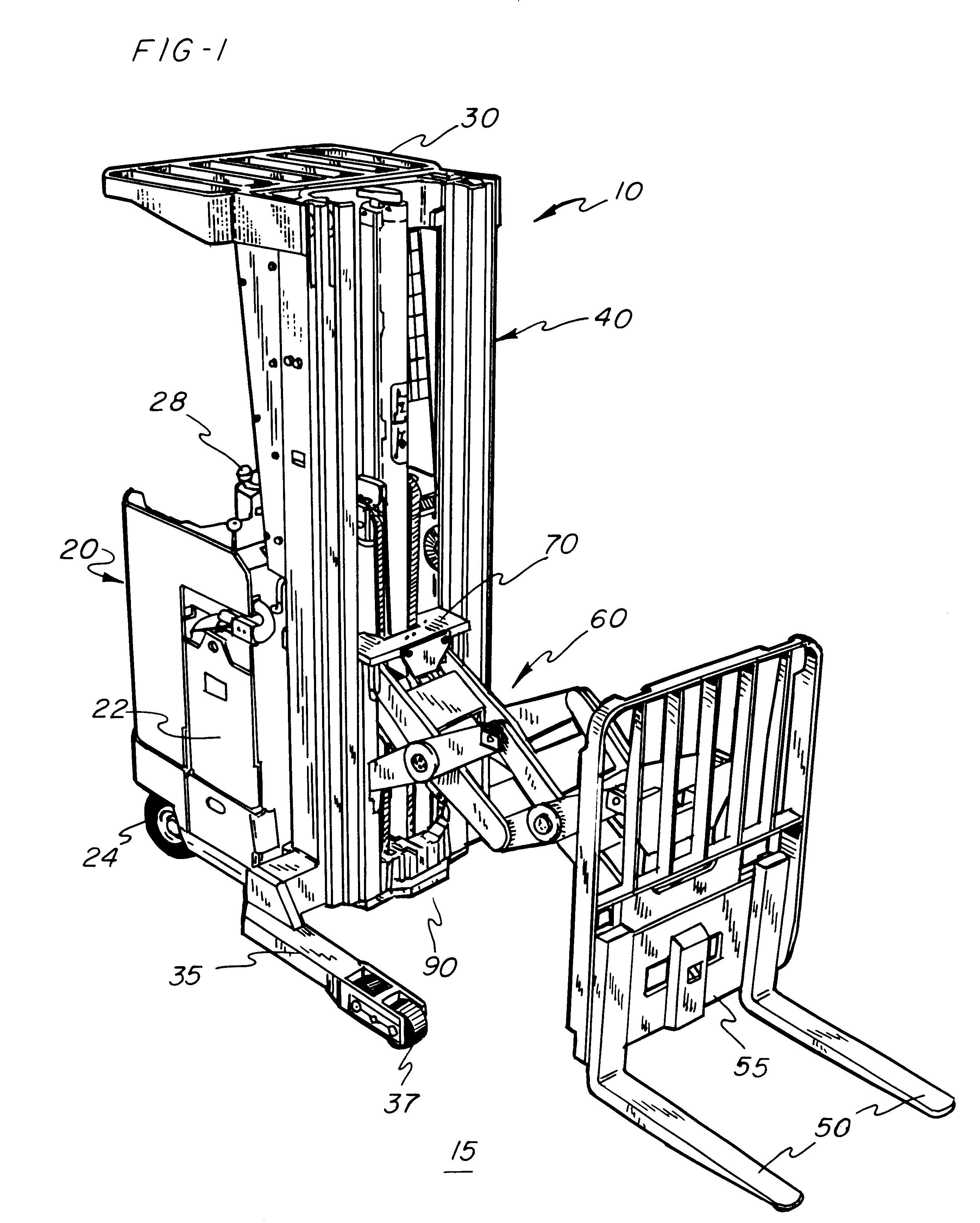
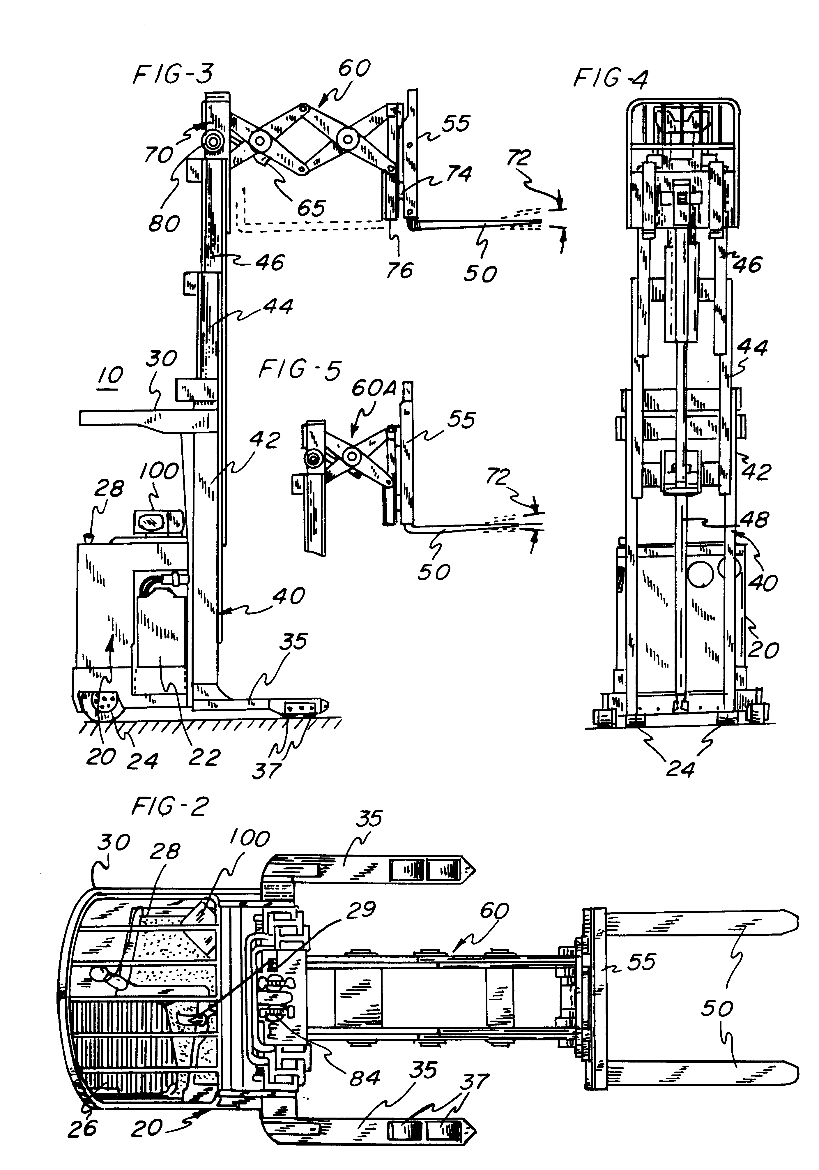
Referring now to the drawings, and particularly to FIGS. 1-5, a self propelled rider-reach lift truck 10 is illustrated as one type of materials handling truck which may incorporate the present invention. The lift truck shown is a model RD 3000 Series truck manufactured by Crown Equipment Corporation, the assignee of the present invention. It is to be understood, however, that other fork lift trucks could also incorporate the present invention, such as Crown models FC, RC, RR, SC and W fork lift trucks.

The truck 10, which operates on floor 15, includes a body 20 that contains a battery 22 supplying power to the truck and various other components, such as electric traction motors (not shown) connected to steerable wheels 24 and hydraulic motors (not shown) which supply hydraulic pressure to fork lift cylinders, as will be explained. An operator's compartment 26 is included on the body 20, along with steering control 28 and control handle 29, which controls the operation of various fu...


PUM


Abstract

A fork lift truck includes a fork level sensor located in the forks, away from the vertical mast of a lift truck for detecting the true level of the forks, and a vision system including a camera which may take several forms. In one form, a single camera is mounted in a housing which may be moved to a protected location vertically either by sliding in the carriage assembly, or by use of a parallelogram device. In another form, multiple cameras are employed where a second camera may be either mounted above the first camera in the same housing or mounted between the forks. Alternatively, the first camera may perform multiple roles by being moved vertically from a first predetermined location below the bottom of the forks to a higher elevation a second predetermined location relative to the forks. A video display terminal, which shows the view observed by the camera, may also include a fork level indicator, a reticle for assisting in adjusting the vertical position of the forks, and an indicator showing the specific truck function selected by the operator.

Description

BACKGROUND OF THE INVENTIONThis invention relates to a remote viewing method and apparatus for use on fork lift trucks. This invention has particular application to those fork lift trucks where the forks can be raised above the head of the operator causing the operator difficulty in visually aligning the forks to a load or a load on the fork to an opening in a storage rack.In many materials handling vehicles, such as a rider-reach truck or a three- or four-wheel counterbalanced truck, a pair of movable, load carrying forks are mounted on a carriage for vertical movement on the mast of the truck. A camera has sometimes been mounted near the heel of the forks to view the scene in front of the forks, and to display that scene on a monitor mounted in view of the operator. Such an arrangement is helpful, provided the camera is properly positioned so that its view is properly aligned with the forks; however, the view of a camera in this location will be blocked when a pallet is placed on ...

Claims


Application Information

Patent Timeline
IPC IPC(8): B66F9/12B66F9/075B66F9/16
CPCB66F9/0755B66F9/122B66F9/16
Inventor DAMMEYER, NED E.FULLENKAMP, TODD M.STAMMEN, HAROLD A.
Owner CROWN EQUIP CORP
Why Eureka
Try Eureka