Dynamic orthopedic knee brace assembly

a knee brace and dynamic technology, applied in the field of dynamic knee brace assembly, can solve the problems of inability to prevent anterior translation of the tibia, and achieve the effects of simple construction, low manufacturing cost, and reliable operation

Inactive Publication Date: 2001-07-24
SMITH III KIRBY
View PDF24 Cites 50 Cited by
  • Summary
  • Abstract
  • Description
  • Claims
  • Application Information

AI Technical Summary

Benefits of technology

It is a further object of this invention to provide a knee brace assembly for restricting abnormal anterior tibial movement without preventing the wearer from being able to fully extend his / her leg.
It is a further object of this invention to provide a knee brace assembly that is inexpensive to manufacture.
It is a further object of this invention to provide a knee brace assembly that is reliable in operation.
It is a further object of this invention to provide a knee brace assembly that is simple in construction.
It is a further object of this invention to provide a knee brace assembly that is lightweight.
It is a further object of this invention to provide a knee brace assembly that is comfortable when worn.

Problems solved by technology

However, this brace suffers from failing to be able to prevent anterior translation of the tibia by the application of posterior pressure directed at the tibia tubercle location.

Method used


Image

  • Dynamic orthopedic knee brace assembly
  • Dynamic orthopedic knee brace assembly
  • Dynamic orthopedic knee brace assembly

Examples


first embodiment

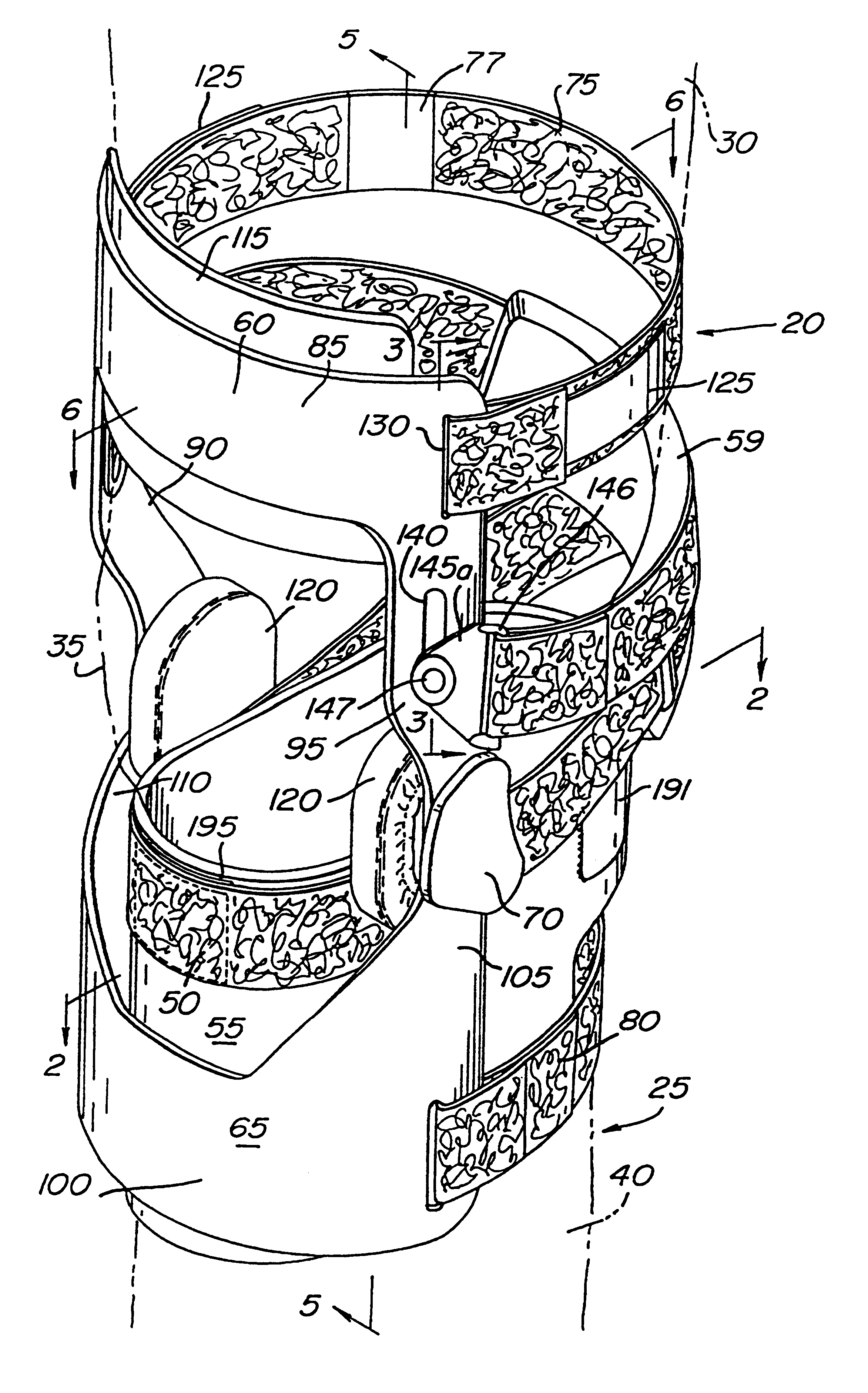
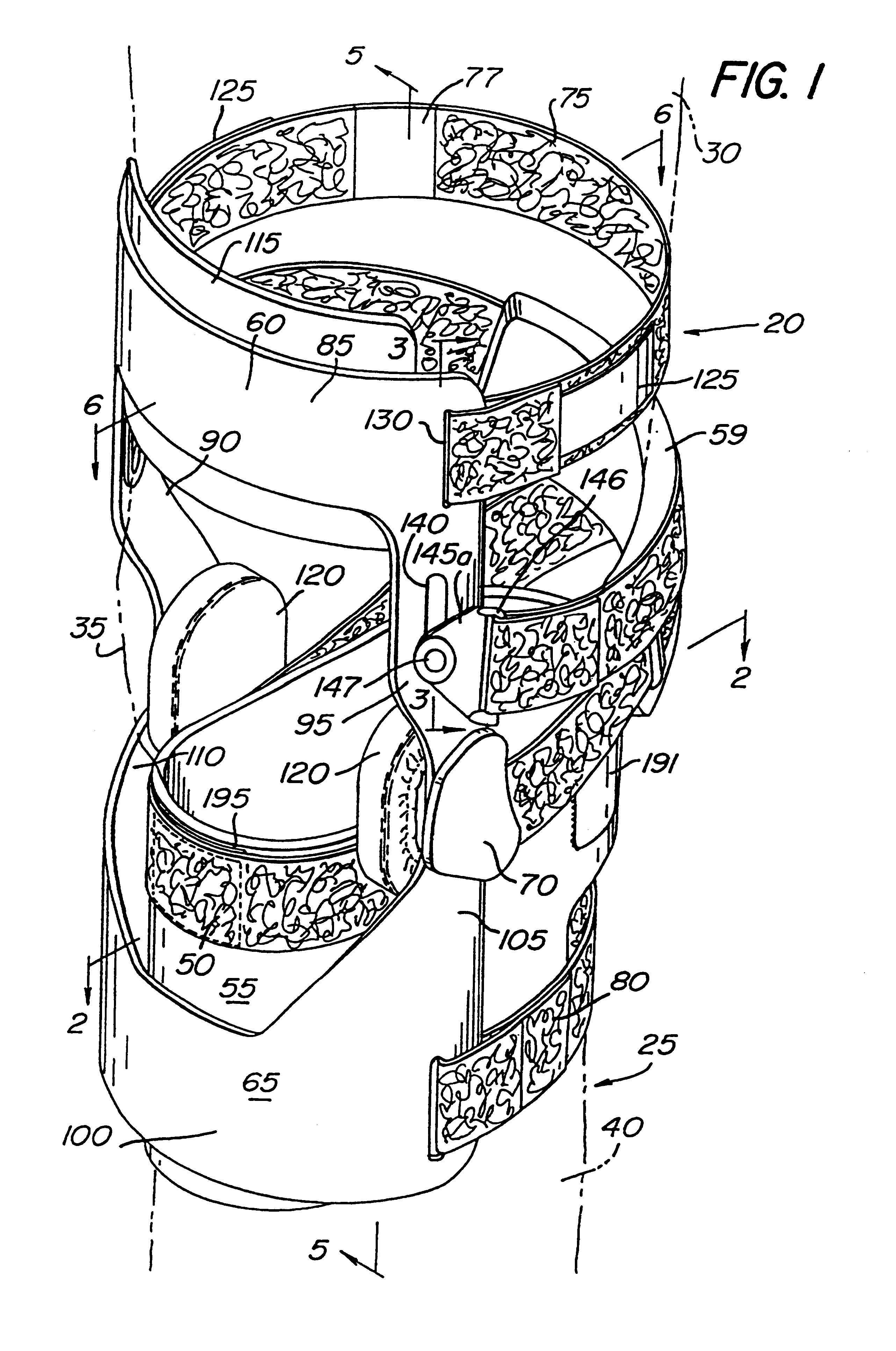
Referring now in greater detail to the various figures of the drawings wherein like reference numerals refer to like parts there is shown at 20 in FIGS. 1, 5 and 7 the dynamic orthopedic knee brace assembly of the present invention. As shown in FIGS. 1 and 5, the knee brace assembly 20 is shown attached to a human left leg 25 (shown in phantom) having a thigh portion 30, a knee 35 and leg portion below the knee 40. The left leg 25 is chosen for convenience only and the brace assembly 20 can be affixed to either the right or left leg. Generally speaking, the knee brace assembly 20 functions to counteract anterior shifting of the tibia when the anterior cruciate ligament in the illustrated leg is missing or damaged. Such anterior shifting of the tibia occurs for a variety of reasons and often occurs when a person is engaging in physical activities that involve sudden turning to the right or to the left, sudden stopping, jumping, running backwards or other types of movement. Where the ...

second embodiment

Referring now to FIGS. 8 and 14, there is shown at 300 the dynamic orthopedic knee brace assembly of the present invention. As best shown in FIG. 14, the knee brace assembly 300 shown therein comprises three basic parts: a bracing component 305, a cross-strap 310 and a sleeve 315. The knee brace assembly 300 functions to counteract anterior shifting of the tibia that can occur during physical activities that involve sudden turning to the right or left, sudden stopping, jumping or running backwards when the anterior cruciate ligament in the illustrated leg is missing or damaged.

As best shown in FIGS. 8 and 14, the bracing component 305 comprises a pair of elongated rigid thigh support members 320 and 325 extending along medial and lateral sides of the thigh, respectively, and a pair of elongated rigid lower leg support members 330 and 335 extending along the medial and lateral sides of the wearer's leg portion below the knee, respectively. The inner ends of the thigh and lower leg su...


PUM


Abstract

A knee brace assembly for various uses, e.g., restricting anterior tibial movement. The knee brace assembly includes a proximal cuff for engaging the wearer's leg above the knee and a distal cuff for engaging the wearer's leg below the knee. The proximal and distal cuffs are linked together by a hinge that permits pivotal movement of the proximal cuff relative to the distal cuff. The proximal cuff has lateral and medial portions each having a slot extending there along. A strap guiding assembly is slidably mounted within each of the slots. Each strap guiding assembly is arranged to slide between a proximal extreme when the wearer's leg is in flexion and a distal extreme as the wearer extends his or her leg. A biasing device biases each strap guiding assembly towards its proximal extreme. A cross-strap, having free ends and a length, is provided for engagement with the wearer's leg. The cross-strap attaches to the wearer's leg below the knee and wraps behind the knee in crisscross fashion. The free ends of the strap attach to the strap guiding assembly. The cross-strap is operative in response to extension of the wearer's leg to pull the strap guiding assembly from the proximal extreme towards the distal extreme thus creating a force counteractive to abnormal anterior movement of the tibia.

Description

This invention relates generally to orthopedic knee braces, and more particularly to knee braces for use by persons having anterior cruciate ligament laxity or insufficiency to protect them from injury due to abnormal anterior tibial movement.BACKGROUND OF THE INVENTIONVarious types of knee braces are shown in the patent literature and are commercially available. The following constitute examples of prior art braces that deal with restricting anterior movement of the tibia: U.S. Pat. Nos. 4,9055,369 (Bledsoe et al.); 5,433,699 (Smith, III); 4,751,920 (Mauldin et al.) and 4,781,180 (Solomonow). The apparatus shown by Mauldin is a knee brace that has a first attachment portion to attach the brace to the wearer's thigh and a second attachment portion to attach the brace to the wearer's tibia and a hinge connected to the medial side of the first and second attachment portions by way of a thigh bar and tibia bar, respectively. An adjustable gearing mechanism located at the hinge permits ...

Claims


Application Information

Patent Timeline
Patent Type & Authority Patents(United States)
IPC IPC(8): A61F5/01
CPCA61F5/0123
Inventor SMITH, III, KIRBY
Owner SMITH III KIRBY
Why Eureka
Try Eureka