

Collectorless direct current motor, driver circuit for a drive and method of operating a collectorless direct current motor
a driver circuit and direct current motor technology, applied in the direction of motor/generator/converter stopper, dynamo-electric converter control, instruments, etc., can solve the problems of impediment to the integration of components and a large amount of additional power loss, and achieve the effect of low power loss in the components and constant operating voltag
Inactive Publication Date: 2002-03-19
PAPST MOTOREN GMBH & CO KG
View PDF37 Cites 23 Cited by
- Summary
- Abstract
- Description
- Claims
- Application Information
AI Technical Summary
Benefits of technology
It is an object of the invention to make available a driver circuit for a collectorless direct current motor so as to permit changes in output power and number of revolutions with small amounts of circuitry and at a constant operating voltage; power losses in
Problems solved by technology
Although this does not produce any additional high frequency fields which could interfere with the devices to be ventilated and such a regulation does not produce any additional noise, a cons
Method used
View moreImage
Smart ImageViewing Examples

Examples
 PUM
 Abstract
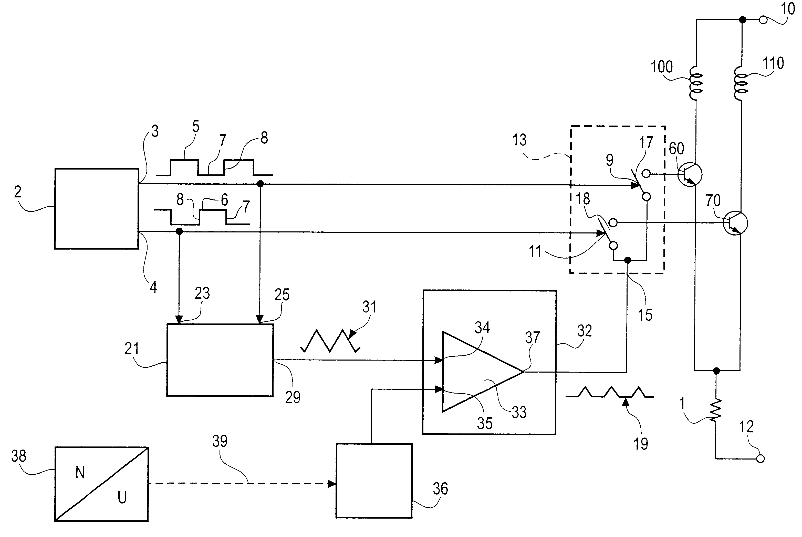
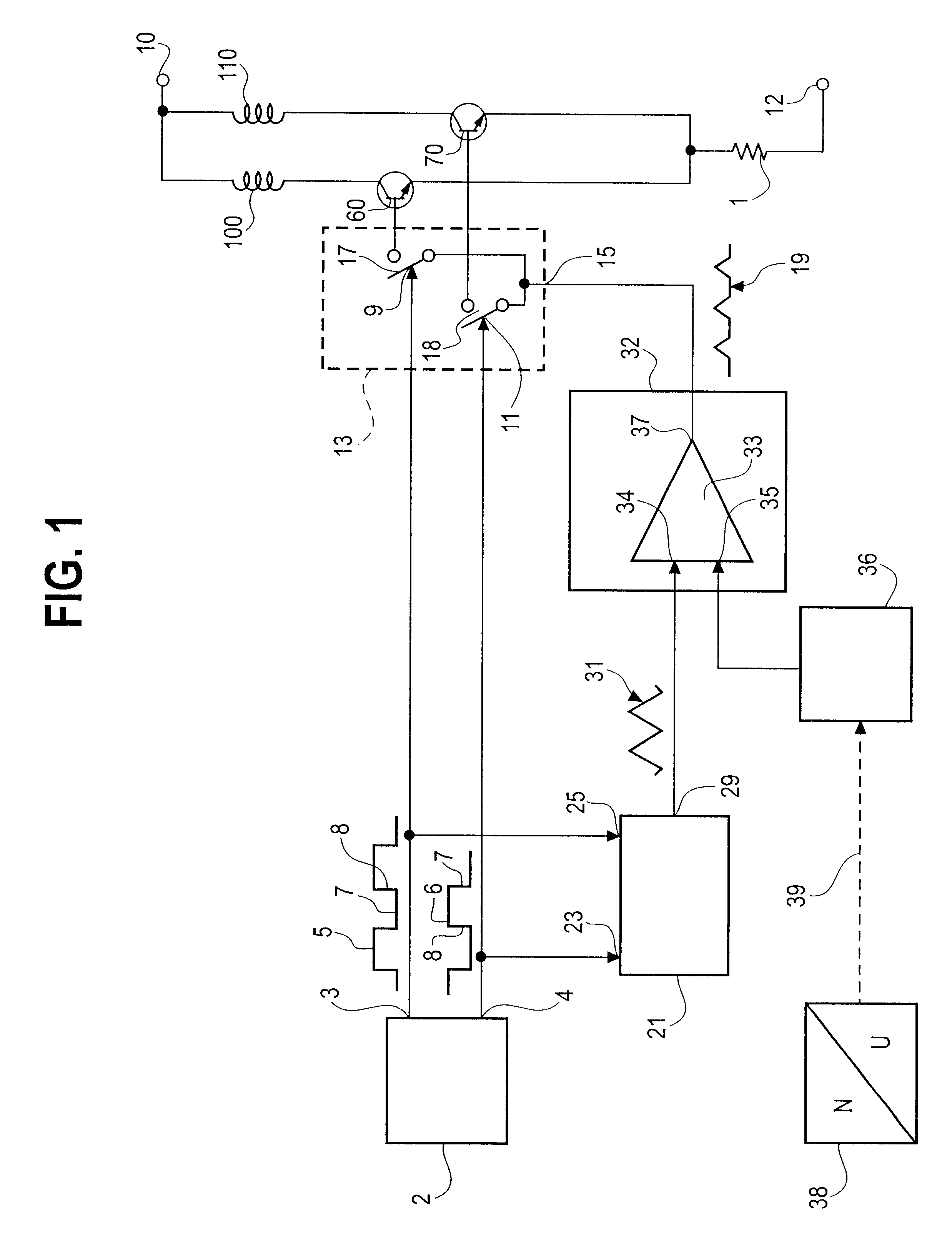
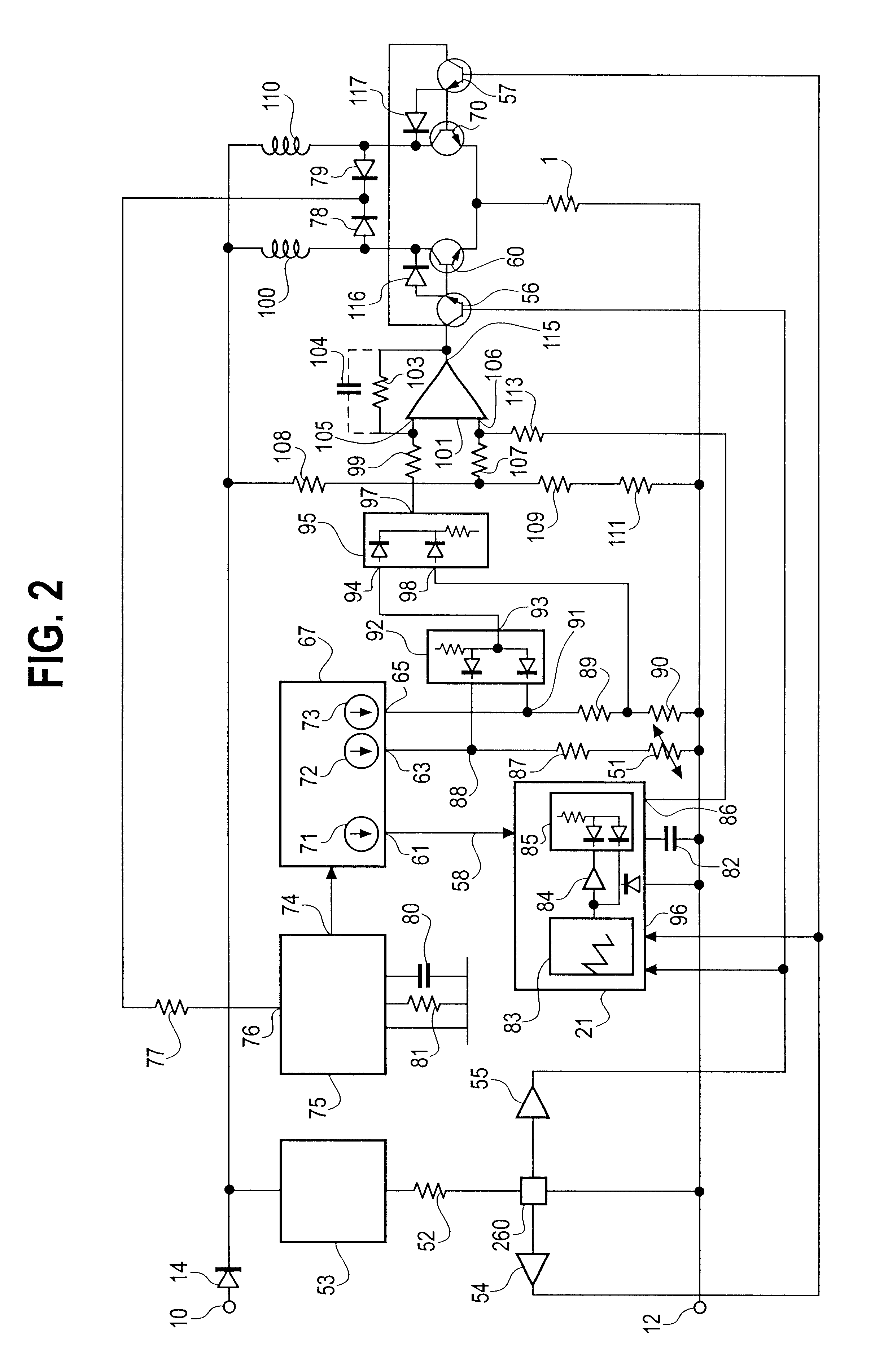
A method for the low-loss regulation of a collectorless direct current motor and a semiconductor circuit has, during the commutation phase given by a position sensor and with reduced motor output and number of revolutions, transistors or one end transistor which initially operates temporarily as a switch and thereafter operates temporarily as an analog amplifier element. During the analog period, a current is available which changes slowly according to a ramp function.
Description
BACKGROUND OF THE INVENTIONThe present invention relates to a collectorless direct current motor equipped with a fan or for driving a fan and including a permanent magnet rotor in the field of at least one stator winding and to a method of operating such a motor. In particular, the invention relates to a driver circuit for a collectorless direct current motor including a permanent magnet rotor having at least two poles and at least one stator winding connected to the driver circuit end stage which temporarily operates as a switch and a sensor detecting the position of the rotor, with the control signal fed to the end stage during each commutation phase causing the current in the stator winding to have a ramp-shaped configuration.Such a driver circuit is disclosed in No. DE-OS 3,107,623 and includes an RC member with the aid of which rectangular signals are reshaped to control the direct current motor in order to reduce the steepness of their edges, thus reducing the winding noise of...
Claims
Login to View More Application Information
Patent Timeline
 IPC IPC(8): H02P6/08G05D23/24H02P6/00H02P6/14
CPCG05D23/1913G05D23/24H02P6/08H02P6/14H02P6/34
InventorMUELLER, ROLF
OwnerPAPST MOTOREN GMBH & CO KG