Laryngoscope blade

a technology of laryngoscope and blade, which is applied in the field of laryngoscope, can solve the problems of inability to achieve optimal visualization of vocal cords, inability of intubator to determine when the tip is in the proper position, and inability of intubator to visualize the blade tip optimally, so as to achieve better visualization of the larynx

Inactive Publication Date: 2002-09-24
SCHNEIDER CARY N
View PDF23 Cites 24 Cited by
  • Summary
  • Abstract
  • Description
  • Claims
  • Application Information

AI Technical Summary

Benefits of technology

Accordingly, it is a principal object of the invention to provide an improved laryngoscope blade which produces better visualization of the larynx through adjusting the curvature of the blade.
The invention also provides the tip of the blade with a small reverse curve at the tip of the blade, in order to permit better visualization of the position of the end of the blade.
The laryngoscope blade of the present invention further includes a proximal part which is contoured to the width and shape of the mouth, having a width of up to 6 cm., in order to provide better control of the tongue during laryngoscopy. This configuration is unlike the part of a conventional laryngoscope blade proximal to its connection with the handle, which is used to move the tongue away from the airway and prevent the tongue from obstructing visualization of the larynx. Therefore, present laryngoscope blades have a maximum width of approximately 2 cm.
It is a further object of the invention to provide improved elements and arrangements thereof for the purposes described which is inexpensive, dependable and fully effective in accomplishing its intended purposes.

Problems solved by technology

Although the Macintosh blade is curved, the curvature is greater than the curvature of the airway, hence it does not permit optimal visualization of the vocal cords because the intubator can't see around the curvature of the blade.
Moreover, with both the Miller blade and the Macintosh blade, the intubator has difficulty visualizing the tip of the blade, again due to the shape of the blade and the shape of the airway.
Consequently the intubator has difficulty determining when the tip is in proper position.

Method used


Image

  • Laryngoscope blade
  • Laryngoscope blade
  • Laryngoscope blade

Examples


Embodiment Construction

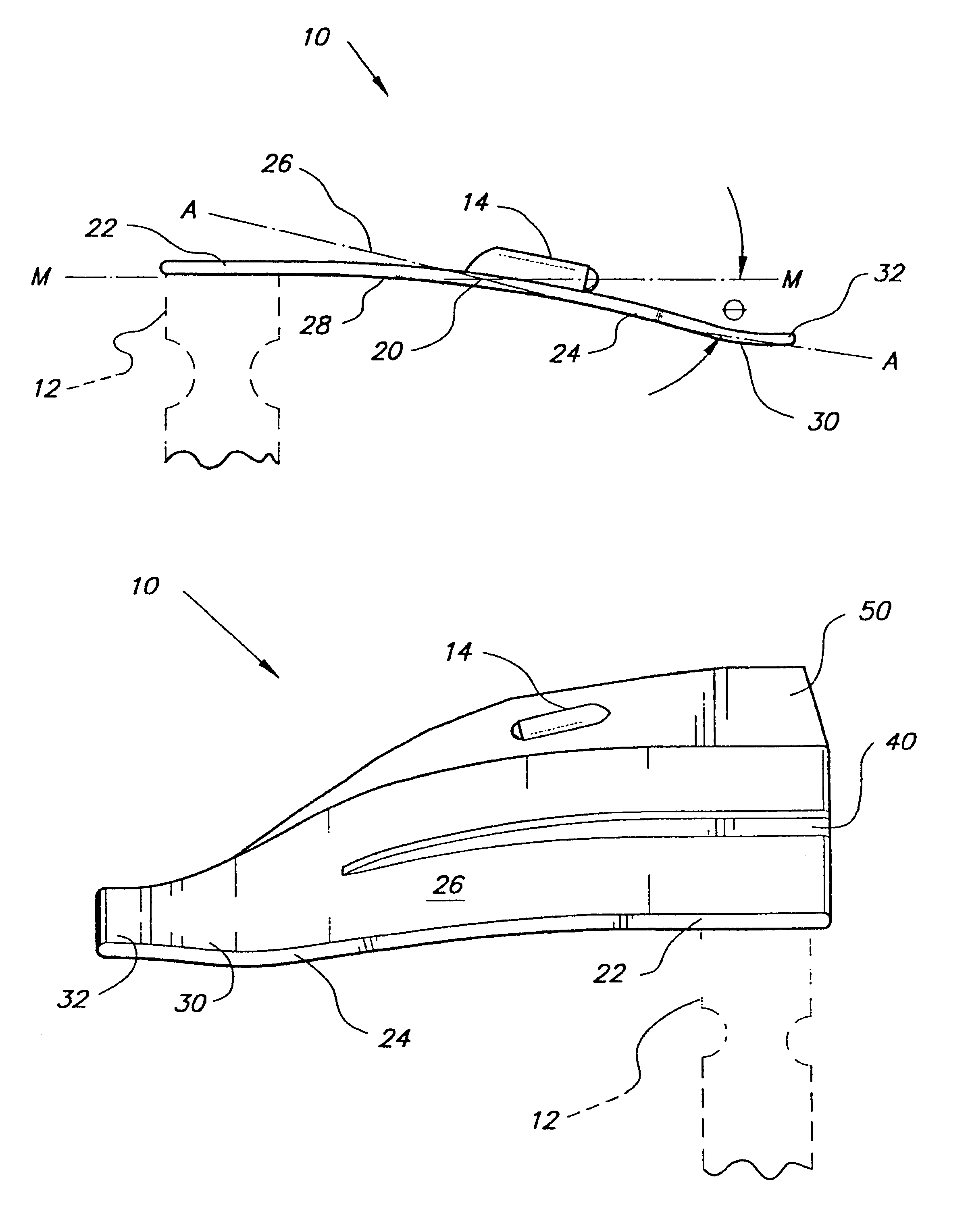
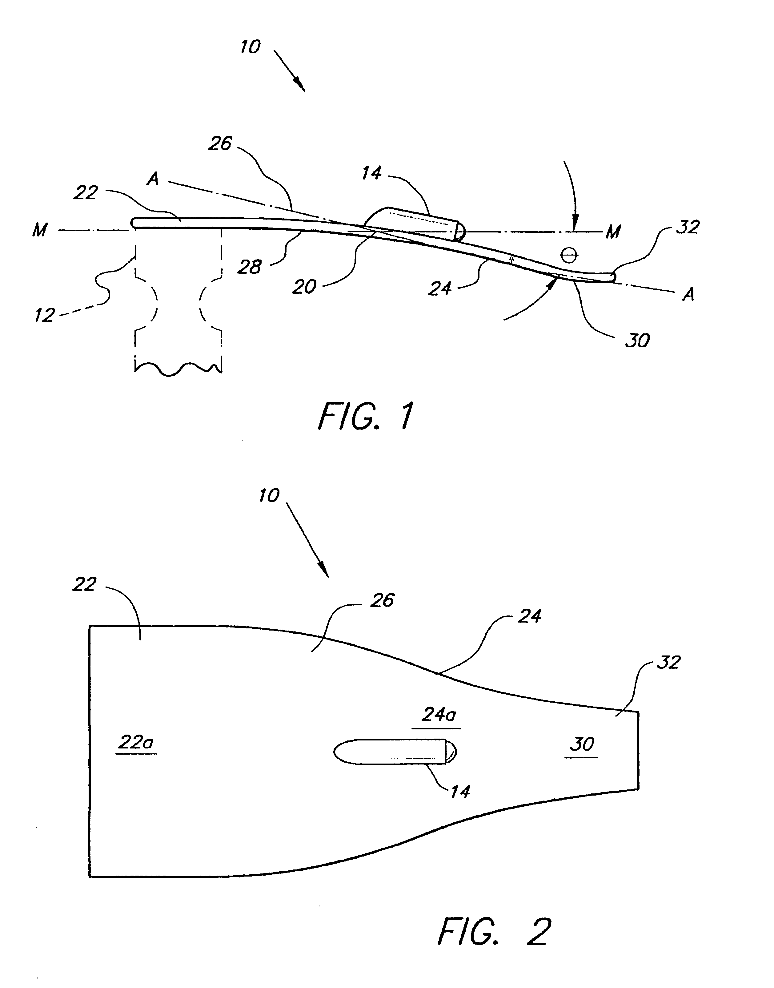
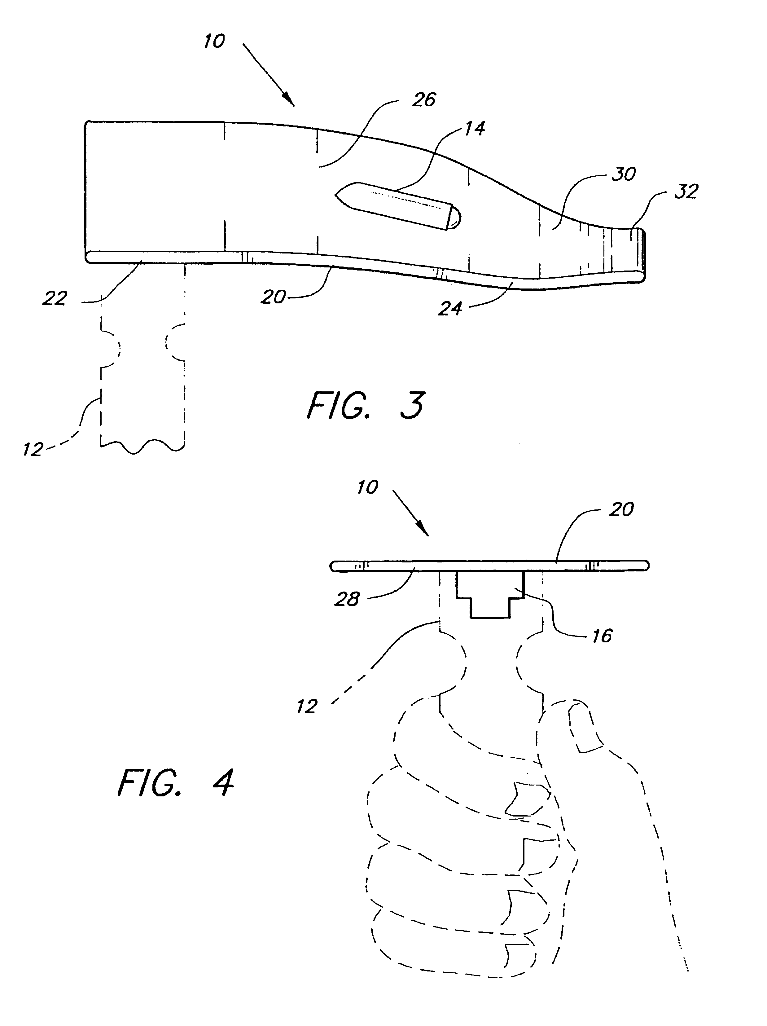
The present invention relates to a laryngoscope with an improved blade. A conventional laryngoscope typically comprises a handle, a blade, and a light source. The blade is usually pivotally mounted on the blade so that the blade is substantially parallel to the handle when not in use, and is substantially perpendicular to the handle to form an L-shape in use.

A variety of arrangements may be used to provide a light source. Power for the light source is usually provided by batteries in the handle. The light source itself may be in the handle with a conduit mounted on the blade, or the light source itself may be mounted on the blade. The connector used to mount the blade may vary depending on the nature of the light source.

The improvement of the present invention does not relate to the handle, the light source, or the means connecting the blade to the handle. As shown more particularly in FIGS. 1 through 4, the present invention relates to the laryngoscope blade 10. The improved blade ...


PUM


Abstract

An improved laryngoscope blade for use with a conventional laryngoscope handle and conventional means for illumination. The improvements to the blade include a small reverse curve at the tip of the blade to better visualize the depth of insertion of the blade, include a greater width of the portion of the blade proximal to the handle to provide improved means for controlling the tongue, and include a more gradual curvature of the blade to better conform to the shape of the airway opening when the patient is properly positioned for laryngoscopy. The blade may also include a vertical wall which may be thickened to serve as a bite block, and raised areas to define grooves on the surface of the blade for insertion of an endotracheal tube and / or a suction catheter.

Description

BACKGROUND OF THE INVENTION1. Field of the InventionThe present invention relates to laryngoscopes, and particularly to an improved blade for a laryngoscope.2. Description of the Related ArtWhile a laryngoscope may be used to visually examine the larynx, its more important function is to aid endotracheal intubation. The need for intubation may arise during a controlled situation, such as surgery, or in a crisis situation when the patient is unable to breathe adequately and requires a resuscitation bag or mechanical ventilation. During intubation, a flexible tube is inserted through the nasal or oral cavity, passed through the larynx, and into the trachea for the administration of gases. The larynx may be viewed as a chamber bounded superiorly by the epiglottis, inferiorly by the vocal cords which cover the opening to the trachea, anteriorly by the thyroid cartilage or Adam's apple, and posteriorly by a portion of the pharynx. The epiglottis is a lamella or leaf-like plate of cartila...

Claims


Application Information

Patent Timeline
Patent Type & Authority Patents(United States)
IPC IPC(8): A61B1/267
CPCA61B1/06A61B1/267
Inventor SCHNEIDER, CARY N.
Owner SCHNEIDER CARY N
Why Eureka
Try Eureka