Angled rotary tissue cutting instrument and method of fabricating the same

a cutting instrument and rotary technology, applied in the field of surgical cutting instruments, can solve the problems of inability to bend, inability to transmit sufficient torque at high speed through angles much greater than 15.degree., and less than 2 bend radii, so as to improve the angled rotary tissue cutting instrument, reduce the radius of curvature of the bend, and increase the range of bend angles

Inactive Publication Date: 2003-03-04
MEDTRONIC XOMED INC
View PDF61 Cites 154 Cited by
  • Summary
  • Abstract
  • Description
  • Claims
  • Application Information

AI Technical Summary

Benefits of technology

Accordingly, it is a primary object of the subject invention to overcome the abovementioned disadvantages of the prior art and to improve angled rotary tissue cutting instruments by providing a rotary tissue

Problems solved by technology

Variable-angle rotary tissue cutting instruments, such as that described in U.S. Pat. Nos. 5,411,514 and 5,601,586 to Fucci et al, permit the user to bend the outer tube to a user-selected angle while still enabling the inner tube to be selectively inserted into and removed from the outer tube; however, known fixed-angle and variable-angle rotary tissue cutting instruments typically have a bend with a radius of curvature on the order of about 2 to 4 inches and are typically not capable of being bent beyond 15.degree..
While the relatively small bend angle and relatively large radius of curvature of these angled tissue cutting instruments is generally suitable for most types of arthroscopic surgery, such instruments are of little use in certain types of head and neck surgery because they are not able to access surgical sites such as the maxillary sinus area which is normally accessed with hand instrum

Method used


Image

  • Angled rotary tissue cutting instrument and method of fabricating the same
  • Angled rotary tissue cutting instrument and method of fabricating the same
  • Angled rotary tissue cutting instrument and method of fabricating the same

Examples


Embodiment Construction

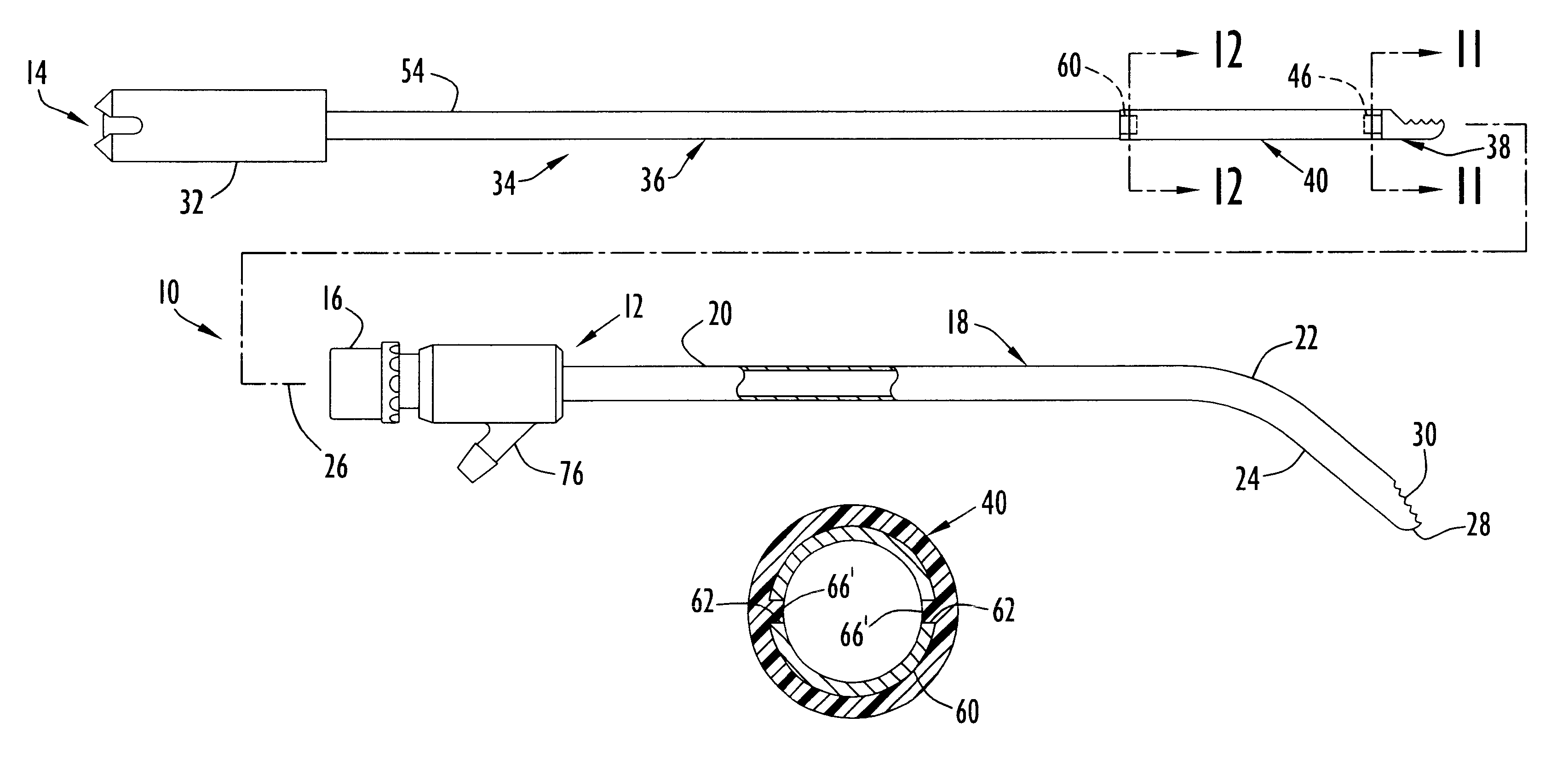
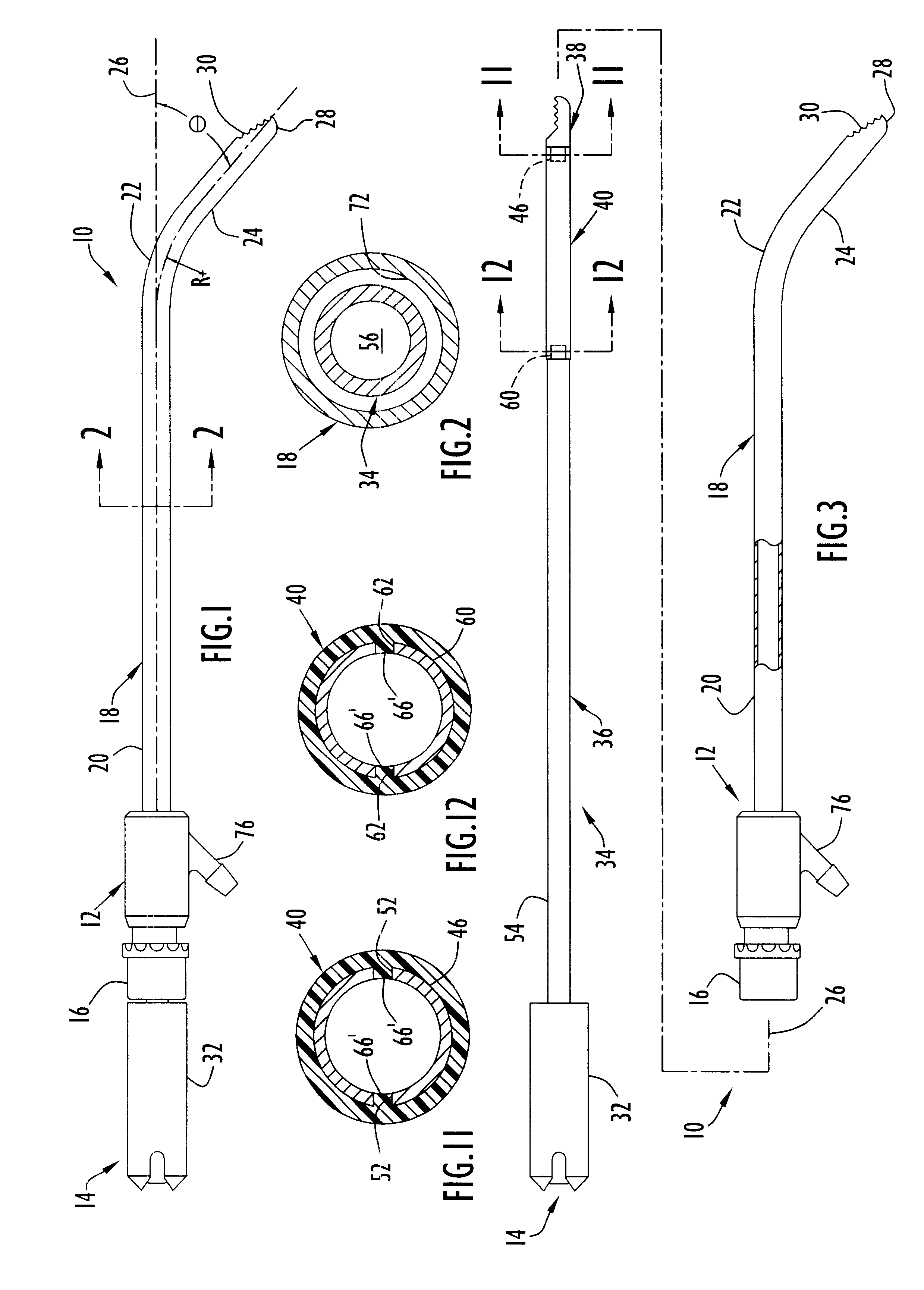
A rotary tissue cutting instrument or blade 10 according to the present invention, as illustrated in FIGS. 1-3, includes an outer blade member or assembly 12 and an inner blade member or assembly 14 rotatably received within the outer blade member. Outer blade member 12 includes a hub 16 and an outer tubular member or sleeve 18 having a proximal portion 20 of straight configuration extending distally from the hub to a bend 22 connecting the proximal portion with a distal portion 24 oriented at an angle .theta. of about 40.degree. relative to the longitudinal axis 26 of the proximal portion. Angled portion 24 of the outer tubular member extends downwardly from bend 22, looking at FIG. 1, to a rounded distal end 28 having an opening facing upwardly, away from the center of curvature of the bend, to define a cutting port or window 30. The orientation of the cutting window as well as the radius of curvature and location of the bend relative to the distal end of the angled portion are de...


PUM

PropertyMeasurementUnit
Lengthaaaaaaaaaa
Lengthaaaaaaaaaa
Lengthaaaaaaaaaa

Abstract

The present invention is generally characterized in an angled rotary tissue cutting instrument including an outer blade assembly, having a rigid tubular member with proximal and distal portions connected by a bead, and an inner blade assembly rotatably disposed within the outer blade assembly and including a tubular drive shaft at a proximal end, a cutting tip at a distal end, and a flexible coupling disposed between the drive shaft and the cutting tip. The drive shaft and cutting tip include neck portions which are disposed telescopically within proximal and distal ends of the coupling. The flexible coupling is formed of a flexible polymeric material, and each of the neck portions includes a lateral opening defining a predetermined flow path for the polymeric material during fabrication so that the flexible polymeric coupling includes flow portions extending into the openings in the neck portions of the drive shaft and the cutting tip to form permanent, interlocking mechanical joints therewith capable of receiving and transmitting torque.

Description

BACKGROUND OF THE INVENTION1. Field of the InventionThe present invention relates generally to surgical cutting instruments and, more particularly, to surgical cutting instruments having an elongate inner member rotatably disposed within an elongate outer tubular member having a cutting window at a distal end which cooperates with or permits the inner member to cut or abrade bodily tissue.2. Discussion of the Related ArtSurgical cutting instruments in which an elongate inner member is rotated within an elongate outer tubular member have become well accepted in surgical procedures where access to the surgical site is gained via a narrow portal or passage. Typically, the outer tubular member includes a distal end with an opening for defining a cutting port or window and the inner member includes a distal end with a cutting tip for engaging bodily tissue via the opening. Proximal ends of the inner and outer members are commonly secured to hubs which attach to a handpiece having a motor...

Claims


Application Information

Patent Timeline
IPC IPC(8): A61B17/32A61B17/28A61B17/00
CPCA61B17/32002A61B2017/00477A61B2017/2904A61B2017/2905Y10T403/477Y10S464/903Y10S285/908Y10T403/48A61B2017/320032
Inventor ANCTIL, STEPHANIE B.PETERS, GARY
Owner MEDTRONIC XOMED INC
Why Eureka
Try Eureka