Attachable electro-impulse de-icer

a technology of electro-impulse de-icer and attached coil, which is applied in the direction of de-icing equipment, aircraft components, transportation and packaging, etc., can solve the problems of accumulating ice on aircraft wings and other structural members in flight, affecting the effect of ice-shedding action, and affecting the effect of ice-shedding

Inactive Publication Date: 2003-03-11
THE BF GOODRICH CO
View PDF20 Cites 35 Cited by
  • Summary
  • Abstract
  • Description
  • Claims
  • Application Information

AI Technical Summary

Benefits of technology

In contrast with prior mechanical de-icers, the de-icer according to the invention is exceedingly effective, while avoiding many of the drawbacks of the prior art. Most of the forces that are applied to the structural member are compressive forces that are more easily accommodated than tensile forces that are produced by various other mechanical de-icers. Further, the device can be fitted readily to structural members, either as part of new construction or as a retrofit.
Because the device operates on an eddy current principle, it completely avoids problems arising from directional current flow, and it provides a more effective ice-shedding action than has been possible with previous devices. In part, the effectiveness of the device is enhanced because the ice-accumulating surface is displaced a relatively great distance at a high rate of acceleration. Although the displacement is not enough to negatively affect the airflow passing over the structural member, the displacement is more than 20 times greater than the displacement that occurs with such devices as are disclosed in prior eddy current-type de-icers. The device also produces about 20% greater eddy current induction than prior internally disposed eddy current de-icers because the coil and the target are in surface-to-surface contact with each other, or nearly so. The referenced internally disposed de-icers require a substantial gap between the coil and the target are in surface-to-surface contact with each other, or nearly so. The referenced internally disposed de-icers require a substantial gap between the coil and the structural member in order to prevent possible damage to the coil upon rebounding of the structural member. The efficiency of the present invention also is great because the ice-accumulating surface that is displaced is relatively thin and is resiliently mounted to the structural member. In those de-icers that distort the structural member itself, the ice-accumulating surface is relatively thick and may be relatively difficult to distort.
.Iadd.Regardless of the embodiment of the invention that is utilized, the sheet-like members can be manufactured readily from metal foil or a flat-braided conductor. The coil according to the invention can be assembled readily, and it provides significant force-generating capabilities compared with prior coil constructions..Iaddend.

Problems solved by technology

The accumulation of ice on aircraft wings and other structural members in flight is a danger that is well known.
While a variety of techniques have been proposed for removing ice from aircraft during flight, these techniques have had various drawbacks that have stimulated continued research activities.
Such expansion typically occurs over approximately 2-6 seconds and results in a substantial change in the profile of the de-icer, thereby cracking accumulated ice.
Unfortunately, expansion of the devices can negatively influence the airflow passing over the aircraft structure.
Also, they are most effective when ice has accumulated to a substantial extent, approximately 0.25 inch or more, thereby limiting their effectiveness.
One of the drawbacks relates to the direction of current flow in adjacent electrically conductive members.
It is believed that the current flow disclosed in the '353 patent produces inefficiencies that significantly restrict the effectiveness of the device.
.Iadd.The accumulation of ice on aircraft wings and other structural members in flight is a danger that is well known.
While a variety of techniques have been proposed for removing ice from aircraft during flight, these techniques have had various drawbacks that have stimulated continued research activities..Iaddend.
Such expansion typically occurs over approximately 2-6 seconds and results in a substantial change in the profile of the de-icer, thereby cracking accumulated ice.
Unfortunately, expansion of the devices can negatively influence the airflow passing over the aircraft structure.
Also, they are most effective when ice has accumulated to a substantial extent, approximately 0.25 inch or more, thereby limiting their effectiveness.
One of the drawbacks relates to the direction of current flow in adjacent electrically conductive members.
It is believed that the current flow disclosed in the '353 patent produces inefficiencies that significantly restrict the effectiveness of the device..Iaddend.

Method used


Image

  • Attachable electro-impulse de-icer
  • Attachable electro-impulse de-icer
  • Attachable electro-impulse de-icer

Examples


Embodiment Construction

The present invention provides a technique especially adapted for de-icing the leading edges of structural members. De-icing is the removal of ice subsequent to its formation upon a leading edge. A leading edge is that portion of a structural member that functions to meet and break an airstream impinging upon the surface of the structural member. Examples of leading edges are the forward portions of wings, stabilizers, struts, nacelles, rotors, and other housings and protrusions first impacted by an airstream.

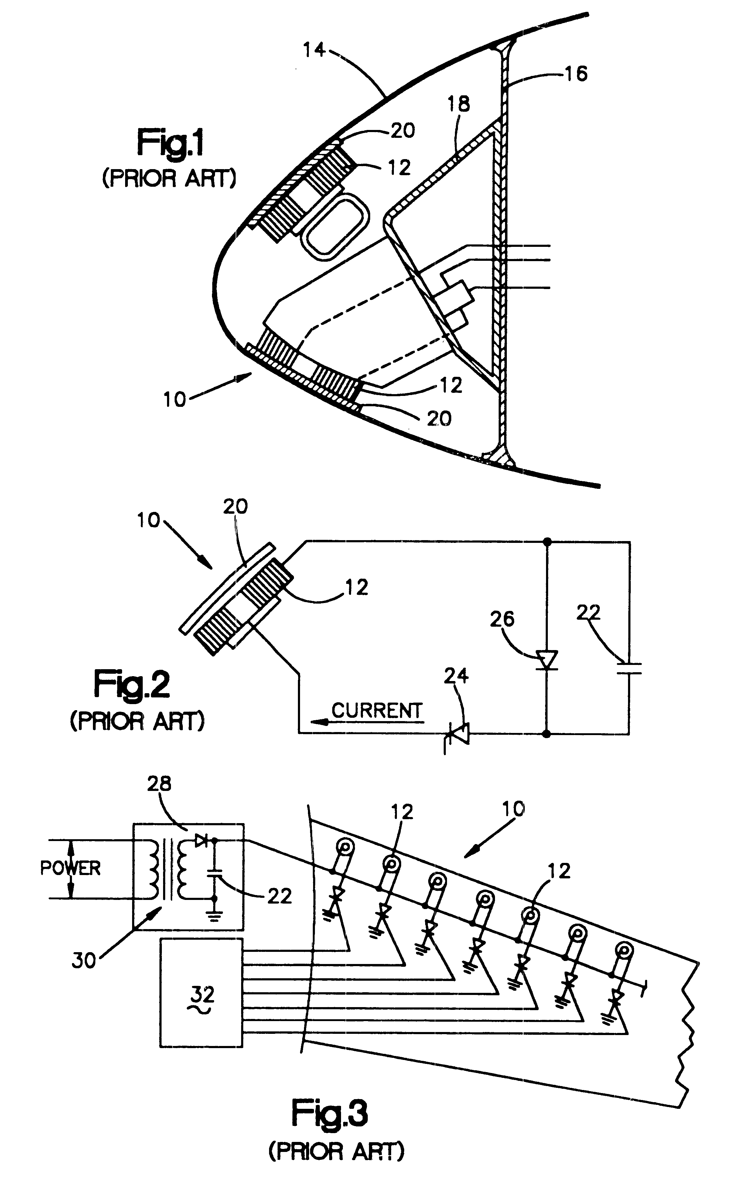
FIGS. 1-3 illustrate a known mechanical de-icer 10 and electrical circuitry thereof. The de-icer 10 includes first and second coils 12 that are disposed with a structural member (such as a wing) 14 near the backside of the leading edge thereof. The surface of the structural member 14 is made of metal such as aluminium which will be referred to as the "skin." The coils 12 are mounted to a spar 16 by means of a mounting bracket 18. The coils 12 are circular in plan view. A circul...


PUM


Abstract

An attachable electro-impulse de-icer for de-icing an aircraft structural member includes an inductor coil disposed in proximity with the outer surface of the structural member. The coil is supported by a flexible, ice-accumulating support member (surface ply) that permits the coil to move relative to the structural member. Preferably the coil and support member are formed in an integral construction that can be attached to the leading edge of the structural member. The coil and support member are rapidly, and forcefully, displaced away from the structural member upon passing a short-duration, high-current pulse through the coil. The current flow creates an electromagnetic field that induces eddy currents in the support member (if made of metal), and the structural member (if made of metal). Upon collapse of the electromagnetic field in the coil the support member is pulled rapidly to its rest position adjacent the structural member. Alternative arrangements are provided wherein (1) a metal target is disposed in proximity with the outer surface of the coil, (2) a metal target is disposed in proximity with the outer surface of the structural member, and (3) an additional target (doubler) is attached to the inner surface of the structural member.

Description

BACKGROUND OF THE INVENTION1. Cross-Reference to Related PatentU.S. Pat. No. 4,875,644, issued Oct. 24, 1989, entitled "Electro-Repulsive Separation System for De-Icing," by Lowell J. Adams, et al., the disclosure of which is incorporated herein by reference (hereinafter referred to as the "Electro-Repulsive Separation System Patent").2. Field of the InventionThe invention relates to de-icers for aircraft and, more particularly, to de-icers that operate by deforming ice-accumulating surfaces..Iadd.The invention relates to planar coils and, more particularly, to planar coils especially adapted for use in a force-producing device such as a de-icer..Iaddend.3. Description of the Prior ArtThe accumulation of ice on aircraft wings and other structural members in flight is a danger that is well known. As used herein, the term "structural members" is intended to refer to any aircraft surface susceptible to icing during flight, including wings, stabilizers, engine inlets, rotors, and so for...

Claims


Application Information

Patent Timeline
Patent Type & Authority Patents(United States)
IPC IPC(8): B64D15/00B64D15/16B64D15/18
CPCB64D15/163
Inventor ADAMS, LOWELL J.WEISEND, JR., NORBERT A.WOHLWENDER, THOMAS E.
Owner THE BF GOODRICH CO
Why Eureka
Try Eureka