Use of a-mode echography for monitoring the position of a patient during ultrasound therapy

a technology of ultrasound therapy and echography, which is applied in the direction of catheters, therapeutic heating, therapeutic cooling, etc., can solve the problems of inability to guarantee the safety of the method, the danger of harming healthy or even vital parts, and the treatment done "blindly" to achieve the effect of simple, accurate and reliabl

Inactive Publication Date: 2003-03-11
TECHNOMED MEDICAL SYST SA
View PDF7 Cites 14 Cited by
  • Summary
  • Abstract
  • Description
  • Claims
  • Application Information

AI Technical Summary

Benefits of technology

The present invention thus sets out to resolve the technical problem of supplying a way of reliably and accurately monitoring the position of a patient during therapy. It would be advantageous if this solution could be particularly simple.
It will be seen that the invention makes it possible to monitor the position of a patient during therapy in a simple, accurate and reliable fashion, thus resolving the technical problems discussed above, as well as providing other technical advantages which will be evident to those skilled in the art.

Problems solved by technology

Treatment that is done "blind" can be dangerous as the sessions are frequently long and the patient--even if anesthetized--may well move.
In this case, there is a danger of damaging healthy or even vital parts.
However, this method does not offer absolute safety as one cannot be sure that the medical personnel will pay sustained attention to the screen displaying the ultrasound image throughout the whole duration of the treatment.
Image analysis techniques have been proposed in order to overcome this disadvantage but these require specific and highly complex electronic systems and software which increases the cost of equipment and can be the source of additional problems.
Another disadvantage of this solution resides in the actual ultrasound scan itself.
This document discloses the incorporation of an ultrasound scanning head into a therapy transducer, but this means that the head masks a portion of the therapy transducer thus reducing the effectiveness of the apparatus, as is pointed out in said application where it is indicated that one always attempts to maximize the transmission surface area of the therapy transducer.
This is a slow process as the image rate is limited by the mechanical scanning of the therapy head.
However, A-mode echography has never been employed at the actual time of therapy and even less for monitoring the position of a patient during therapy.
However, luminous markers can obviously not be employed in certain cases, as is for example the case in endocavital treatment.

Method used


Image

  • Use of a-mode echography for monitoring the position of a patient during ultrasound therapy
  • Use of a-mode echography for monitoring the position of a patient during ultrasound therapy
  • Use of a-mode echography for monitoring the position of a patient during ultrasound therapy

Examples


Embodiment Construction

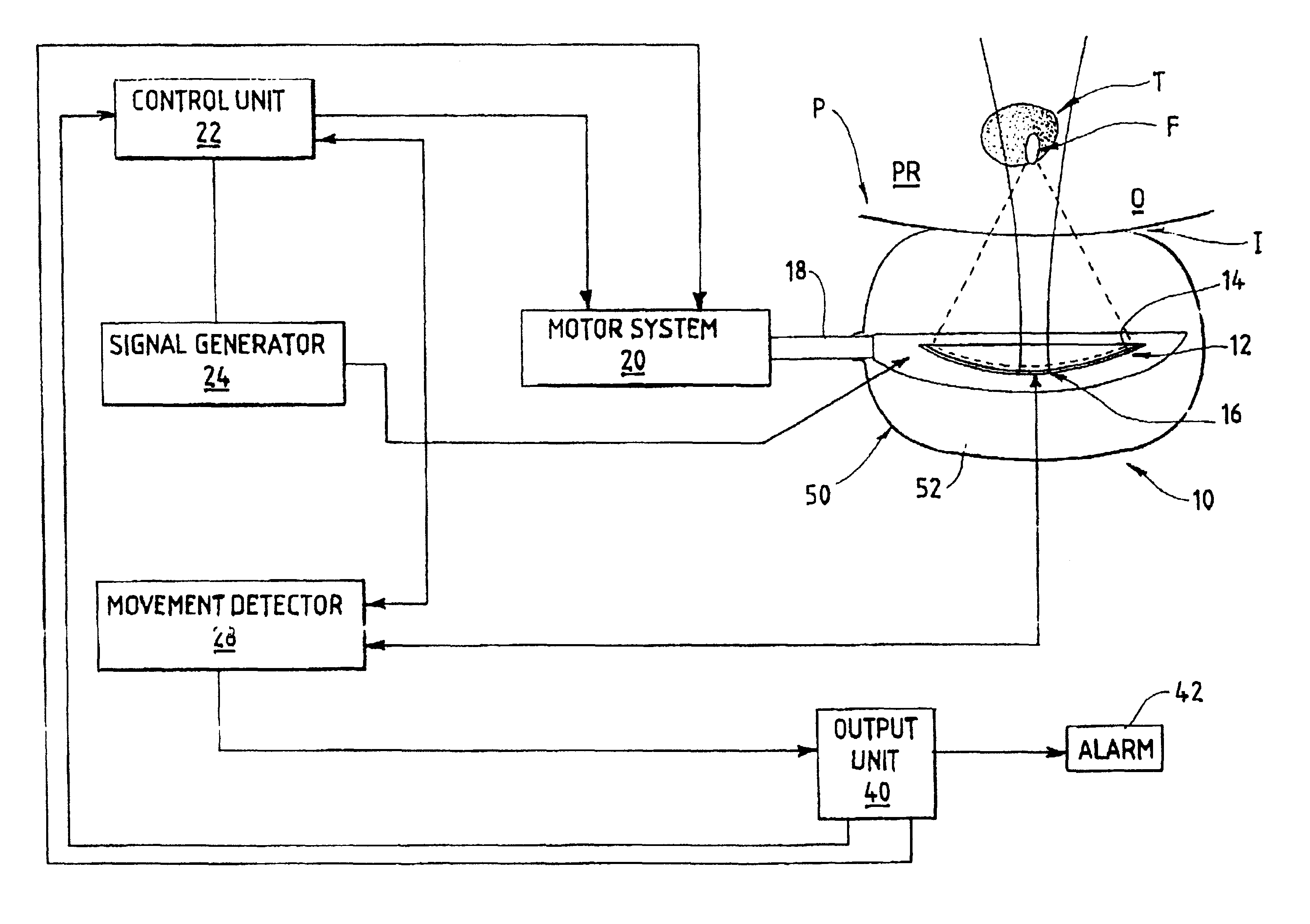
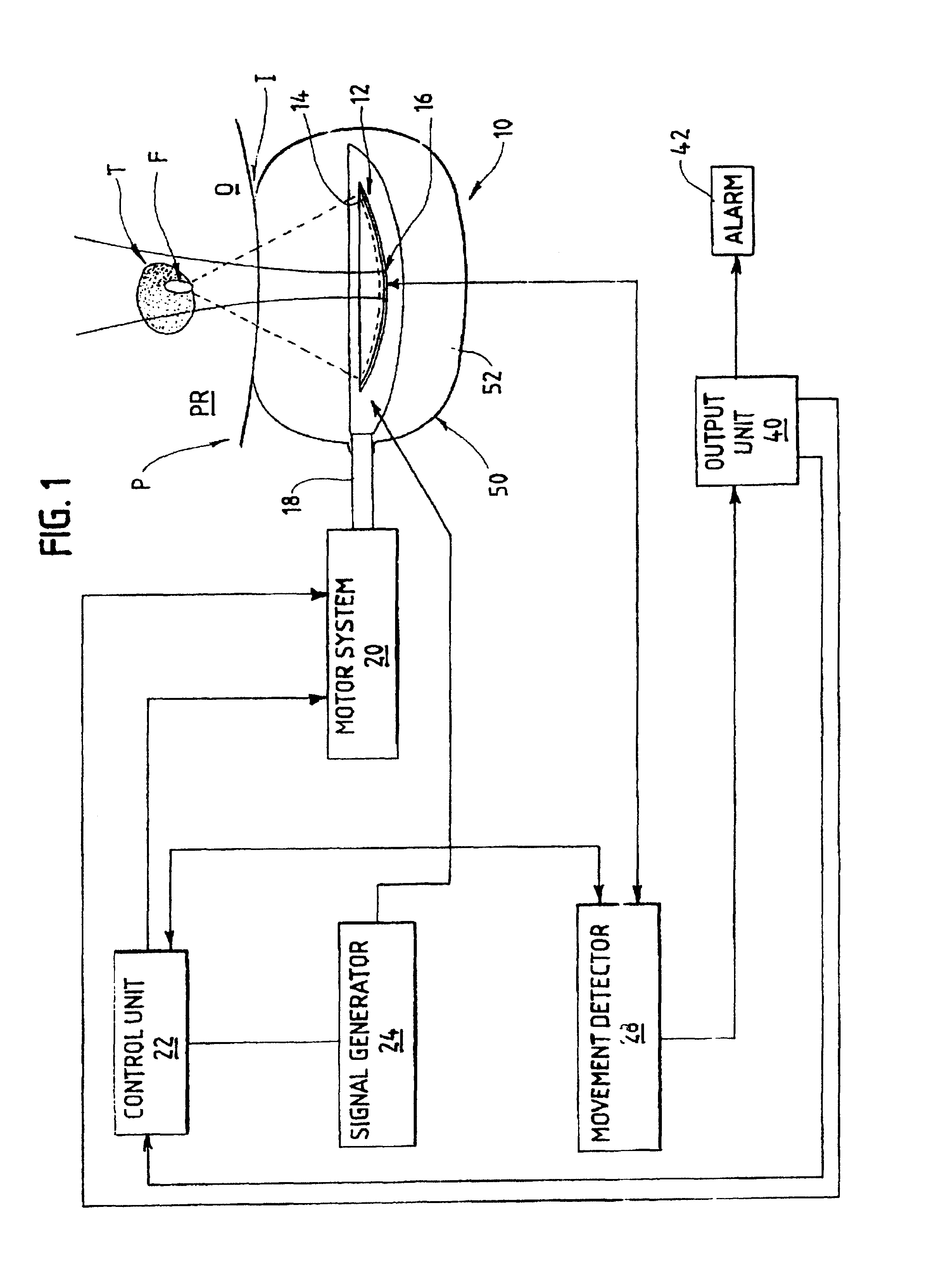
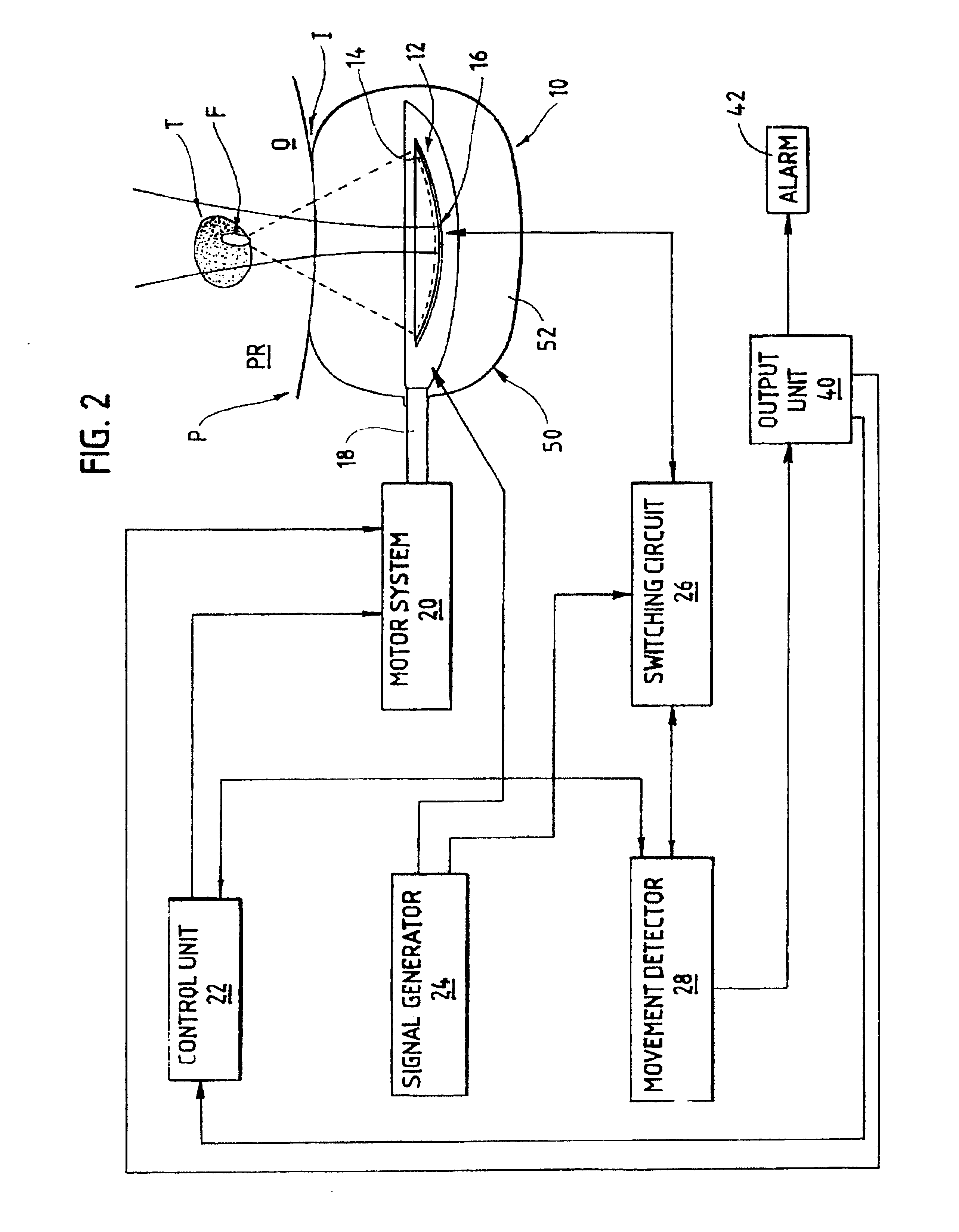
With reference to FIGS. 1 to 4, the therapy apparatus according to the present is generally identified by the reference numeral 10. The therapy apparatus includes an actual therapy device generally indicated by reference numeral 12, including a therapy transducer 14 which here takes the form of a naturally focusing cup-shaped dish, together with at least one ultrasound monitoring transducer 16 linked to an electronic circuit for A-mode echography. Those skilled in the art will readily recognize that the transducer 16 can constitute part of an A-mode echography device.

In one preferred embodiment, the active part of ultrasound monitoring transducer 16 is an integral part of therapy transducer 14 and thus does not constitute a transducer separate from the latter, although such an alternative embodiment would also be possible.

The monitoring element can be situated at the center of the transducer, on its axis of symmetry.

The monitoring transducer can be obtained by partitioning the metal...


PUM


Abstract

An A-mode ultrasound echography method is employed for monitoring the position of a patient during hyperthermia treatment. A therapy apparatus includes a therapy device having at least one ultrasound therapy transducer and at least one monitoring ultrasound transducer, where the ultrasound monitoring transducer is linked to an electronic circuit for processing A-mode signals and is part of an A-mode echography device. The therapy apparatus further includes a device for causing the ultrasound transducer operating in A-mode to transmit a brief signal and to receive the echo of the brief signal. A comparing device compares the echo received with a reference echo, and transmits the result of the comparison to a control device.

Description

BACKGROUND OF THE INVENTIONThis invention essentially relates to the use of an ultrasound echography device operating in A-mode for monitoring the position of a patient during a therapy session, and to a method and apparatus applying it.It is known that focused ultrasound can be used for treating tumors. Generally, this is done in several stages, and more specifically consists in first locating the volume to be treated, then calculating the firing positions and after this directing successive shots to the calculated positions.In accordance with known methods, the shot is either done "blind" or sometimes advantage is taken of the vacant period between shots for providing an ultrasound image for monitoring purposes.Treatment that is done "blind" can be dangerous as the sessions are frequently long and the patient--even if anesthetized--may well move. In this case, there is a danger of damaging healthy or even vital parts.Thus, by providing an image, the actual position of the therapeu...

Claims


Application Information

Patent Timeline
Patent Type & Authority Patents(United States)
IPC IPC(8): A61B8/12A61N7/02A61N7/00A61B19/00A61B17/00A61F7/00
CPCA61B8/12A61B8/4272A61B2017/00119A61B2017/00274A61B2018/00547A61N7/022A61B2090/3784
Inventor CHAPELON, JEAN-YVESBLANC, EMMANUEL
Owner TECHNOMED MEDICAL SYST SA
Why Eureka
Try Eureka