
Phase change analysis in logging method

a phase change and logging technology, applied in the field of down hole fluid sampling tools and methods, can solve the problems of delay between phase change and detection, inability to create bubbles down holes, and generally considered impossible, and achieve the effect of measuring accurately

Inactive Publication Date: 2003-06-03
SCHLUMBERGER TECH CORP
View PDF10 Cites 27 Cited by
  • Summary
  • Abstract
  • Description
  • Claims
  • Application Information

AI Technical Summary

Benefits of technology

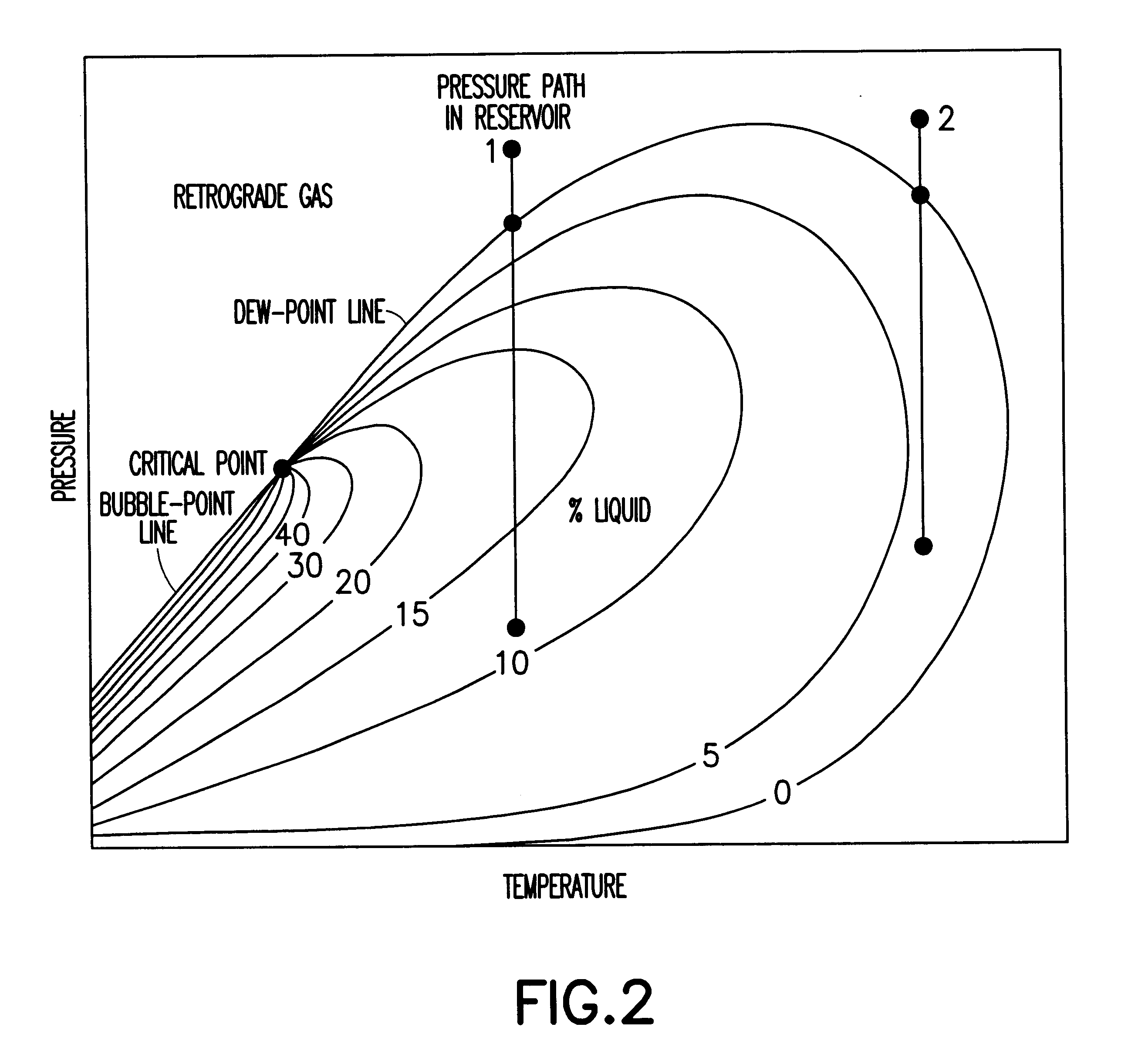
In accordance with the present invention, there is provided an improved method of fluid analysis in the borehole of a well. Fluid sampling tools as well as other down hole tools can be used to measure the bubble point and dew point of the extracted fluids. For example, an MDT tool comprises a pumpout module that can be used to draw fluids from the formation, circulate them through the instrument, and then expel this fluid to the borehole. It has been determined that bubble point and dew point measurements can be measured accurately with a down hole tool, such as an MDT.
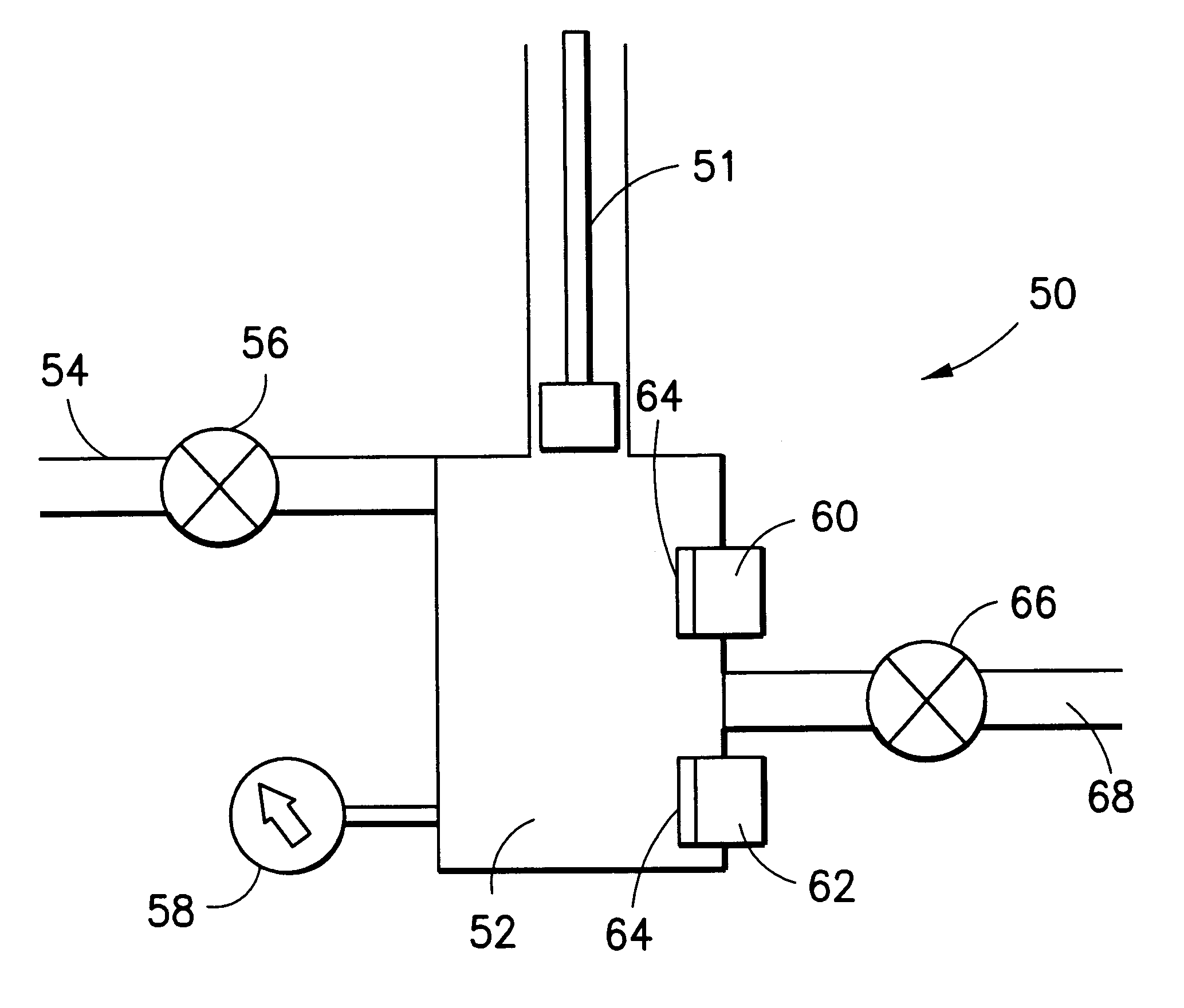
The solution proposed by this invention is to use an ultrasonic transducer in the fluid flowline to create bubbles by cavitation. Cavitation, however, is generally considered to be impossible when fluid pressure is high. Although several hundred psi is a rule of thumb for typical piezoelectric ultrasonic transducers, the pressure in the sampling tool flowline is as high as 20,000 psi. Therefore, it would appear that cavitation is not a viable method of creating bubbles down hole. However, for a fluid at the bubble point (i.e., the point at which bubbles are thermodynamically stable, but form slowly), modest localized pressure reductions, such as are found in acoustic waves, can lead to efficient evolution of bubbles.

Problems solved by technology

Both of these methods are characterized by a delay between the arrival at the thermodynamic phase line and the initiation of phase change, and then a delay between the phase change and its detection.
Cavitation, however, is generally considered to be impossible when fluid pressure is high.
Therefore, it would appear that cavitation is not a viable method of creating bubbles down hole.

Method used


Image

  • Phase change analysis in logging method
  • Phase change analysis in logging method
  • Phase change analysis in logging method

Examples


Embodiment Construction

Generally speaking, the present invention features a method of determining the bubble point and dew point of formation fluids down hole. Extracting fluids from earth formations by means of sampling logging tools is widely known and practiced. "Schlumberger Wireline Formation Testing and Sampling" (1996). The best known commercial tools used for this purpose are the Schlumberger Modular Formation Dynamics Tester (MDT) and the Western-Atlas Reservoir Characterization Instrument (RCI).

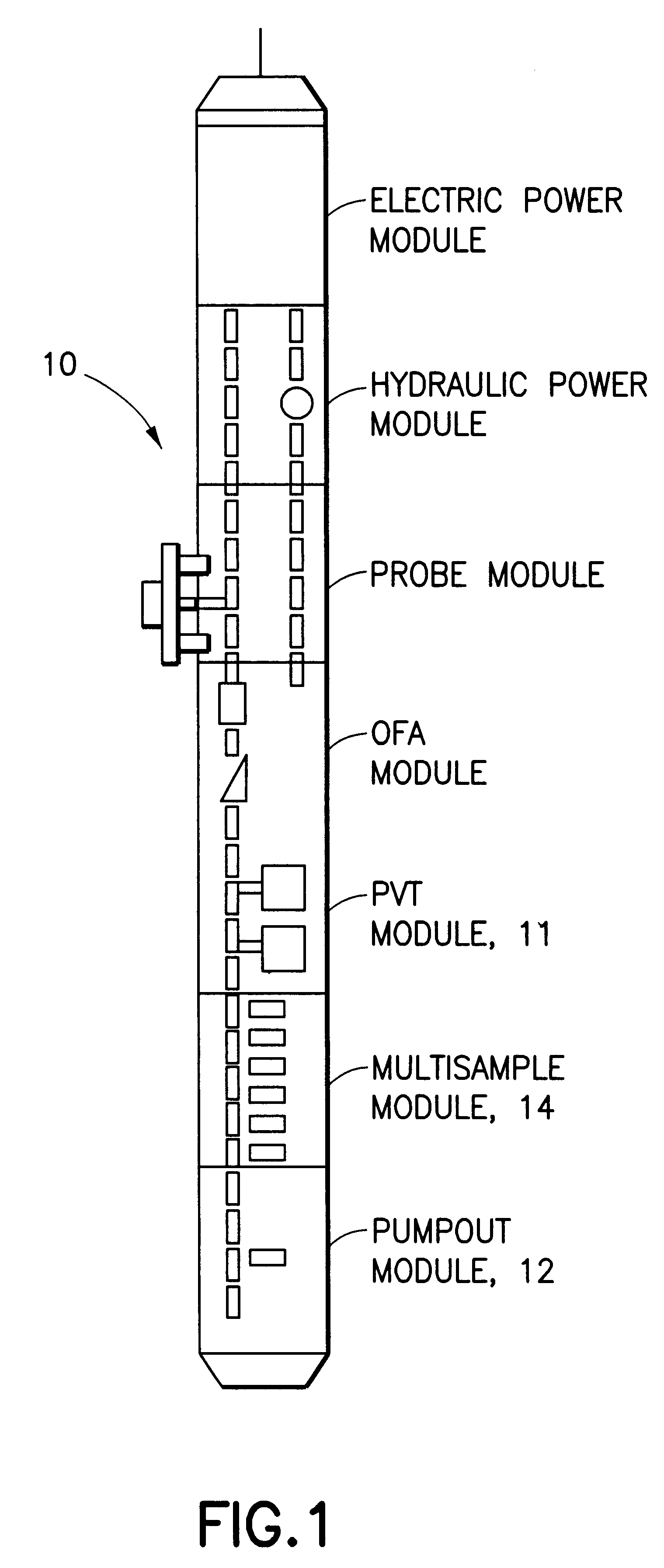
Now referring to FIG. 1, a typical MDT tool 10 having a PVT module 11 is shown.

For purposes of definition herein, tools that extract fluids from formations are generically called "sampling tools". Most commonly, sampling tools pump formation fluid for a substantial period of time in order to minimize contamination by mud filtrate. The MDT tool 10 has a pumpout module 12 for this purpose. During the pumping process, fluid properties are measured by various means, such as low-frequency electrical conductivi...


PUM


Abstract

An improved method of fluid analysis in the borehole of a well. A fluid sampling tool is fitted with a pumpout module that can be used to draw fluids from the formation, circulate them through the instrument, and then expel this fluid to the borehole. It has been determined that certain measurements would be most valuable to implement down hole, such as the formation fluid bubble point and dew point. Accurate bubble point and dew point measurements are made by forming bubbles or a liquid drop in a measured sample, and detecting same.

Description

FIELD OF THE INVENTIONThe present invention relates to down hole fluid sampling tools and methods and, more particularly, to an improved fluid extraction tool and method for analyzing thermodynamic phases of complex fluids down hole.BACKGROUND OF THE INVENTIONSchlumberger Technology Corporation, the assignee of the present invention, has pioneered the use of Modular Formation Dynamics Testers (MDTs) and other down hole tools. The Modular Formation Dynamics Tester is one of several very useful instruments for obtaining formation fluid samples. The MDT tool is suspended by a wire line and then lowered into the borehole of the well. The instrument is secured to the walls of the borehole and samples of the formation fluid are extracted. Such a tool is illustrated in U.S. Pat. No. 4,860,581, issued to Zimmerman et al on Aug. 29, 1989.Fluid sampling tools comprise a pumpout module that can be used to draw fluids from the formation, circulate them through the instrument for analysis, and t...

Claims


Application Information

Patent Timeline
IPC IPC(8): E21B49/08E21B49/00G01N33/28G01N33/26
CPCE21B49/081G01N33/2823E21B49/0875
Inventor KLEINBERG, ROBERT L.
Owner SCHLUMBERGER TECH CORP
Learn More