Recalibrating a multi-color imaging system

a multi-color imaging and recalibrating technology, applied in the field of multi-color imaging technology, can solve the problems of uncalibrated imaging system, inability to accurately represent the output of the target imaging system, and increased possibility of drift and systematic shift affecting the color respons

Inactive Publication Date: 2003-07-15
KODAK POLYCHROME GRAPHICS
View PDF20 Cites 63 Cited by
  • Summary
  • Abstract
  • Description
  • Claims
  • Application Information

AI Technical Summary

Problems solved by technology

Over time, the imaging system can become uncalibrated due to a variety of hardware and material variations.
If the deviation is not eliminated, the imaging system will not accurately represent the output of the target imaging system.
The larger number of hardware and materials variations arising in direct digital color proofing systems, relative to conventional halftone systems, creates a greater possibility of drift and systematic shift that can affect the color response.
Unfortunately, such variations may not be well-corrected by simple one-dimensional linearization of the separated color values in each independent color channel.
One-dimensional linearization of the single color channels independently from one another does not adequately address correction of the color response for admixed colors created by interaction of two or more colorants.
The use of color transformations further complicates the recalibration process.
As discussed above, however, the use of color transformations complicates the problem of recalibration of the digital color proofing system.
Thus, single-channel linearization is made difficult.
Further, standard linearization does not consider second-order effects, such as spatial shifts and interaction between channels.
The visual comparison technique described above works well as a visually based recalibration tool, but is impractical for use as a measurement-based tool.
The large number of patches that would have to be measured for a software-based application to determine the optimal corrections required to gray balance the highlight, quarter-tone, mid-tone, and three-quarter tone grays would be extremely time consuming.
Digital color proofing systems typically are not perfect halftone systems, however, and therefore are less amenable to the use of a measurement-based recalibration tool that directly optimizes the grays and other mixed colors.
Moreover, the digital color proofing system may exhibit significant differences in gamut relative to the target proofing system, and therefore requires color transformations, as described above.
It is difficult to mathematically calculate the effect on grays and chromatic colors due to alteration of the relative CMYK values, particularly when color transformations are being employed.

Method used


Image

  • Recalibrating a multi-color imaging system
  • Recalibrating a multi-color imaging system
  • Recalibrating a multi-color imaging system

Examples


example 1

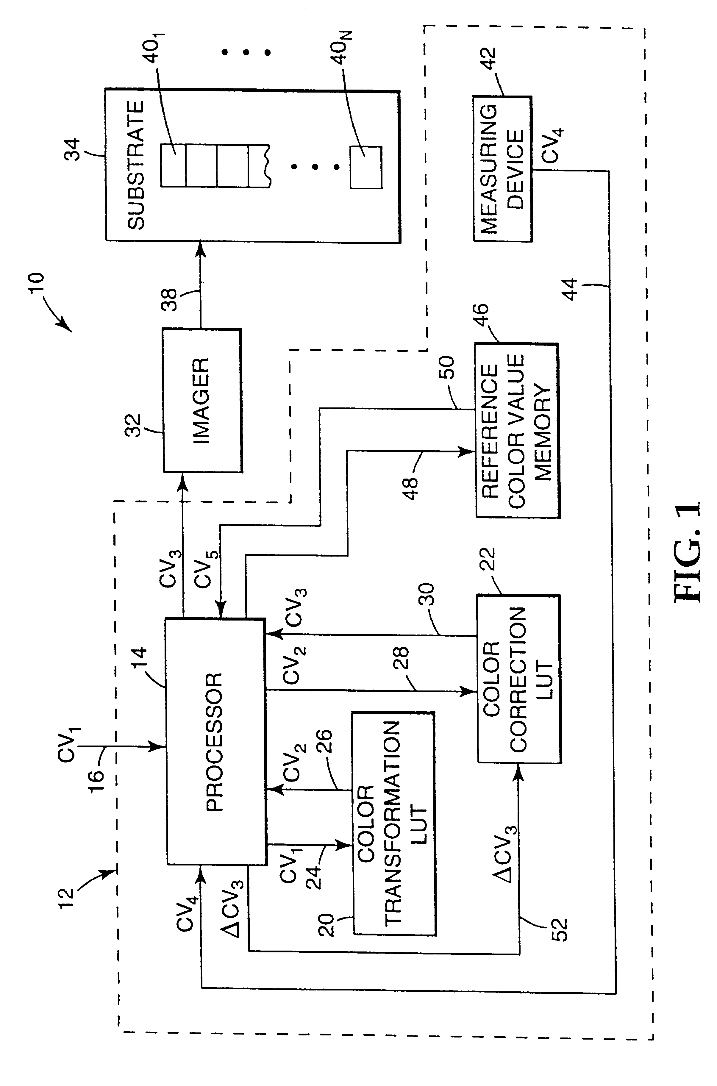
A CMYK proof of an image was made using the 3M Rainbow.TM. digital proofing system as imaging system 10. The color imaging system targeted by the 3M Rainbow system was the 3M Matchprint.TM. III proofing system. The proof was generated by first selecting the MP3 color transform in the color management software provided with the 3M Rainbow.TM. digital proofing system. The MP3 color transform was in the form of a multi-dimensional color transformation LUT, such as LUT 20 in FIG. 1. The MP3 color transform implemented a color transformation function for simulation of the 3M Matchprint.TM. III proofing system. Application of the MP3 color transform to input color values CV.sub.1 produced color-transformed input color values CV.sub.2. Manual adjustments then were made to input color values CV.sub.2 via a color correction LUT, such as LUT 22 in FIG. 1, to produce input color values CV.sub.3 sufficient to produce an acceptable visual match between the output of the 3M Rainbow.TM. imaging sy...

example 2

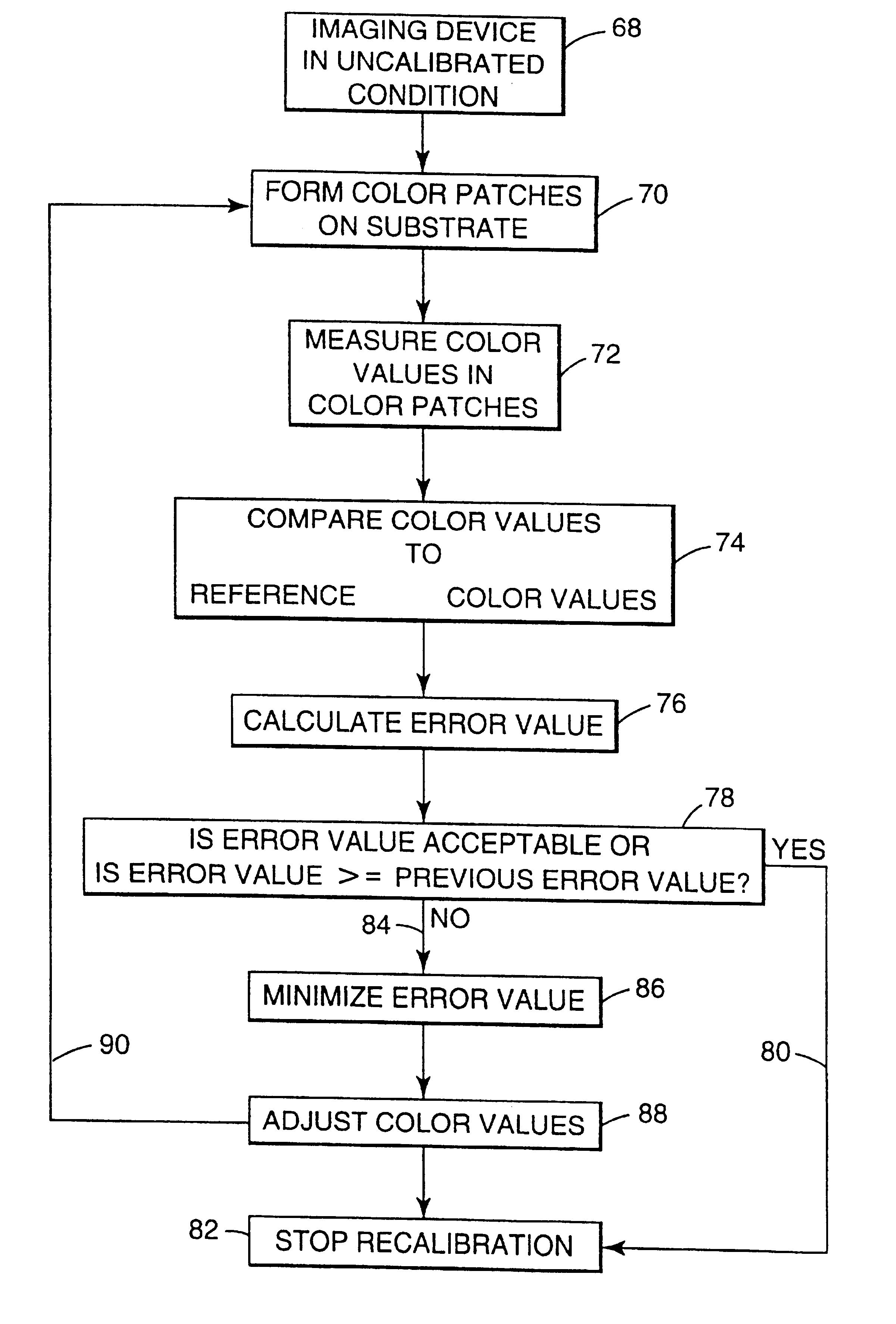
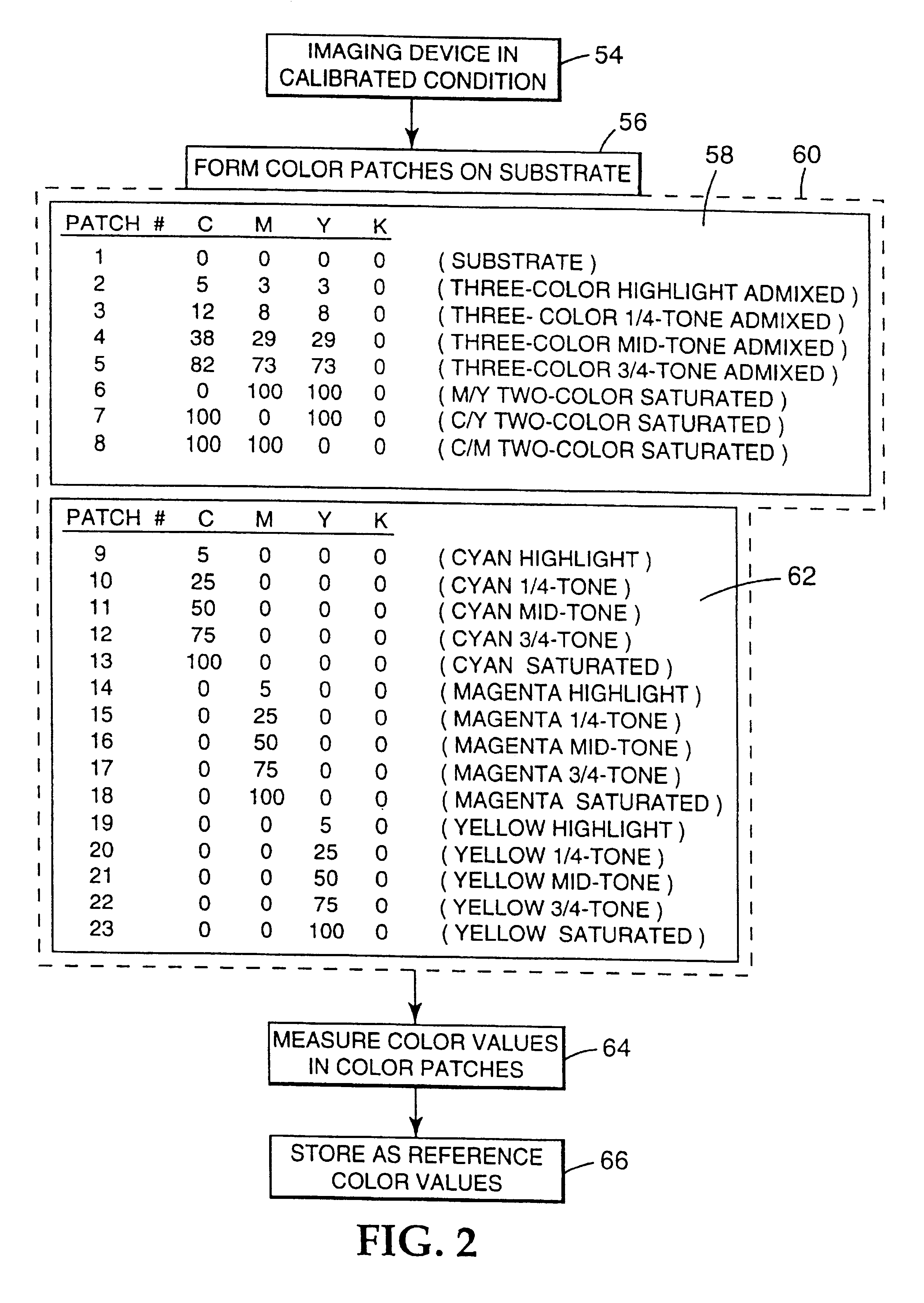
A recalibration procedure substantially similar to that described with respect to EXAMPLE 1 above was performed using the quick recalibration procedure described with reference to FIGS. 2 and 3. The quick recalibration procedure required the formation of only seven color patches, and the measurement of only eight, including the unimaged substrate patch. The results of the quick recalibration mode were similar to those of the comprehensive calibration mode, but slightly less accurate. The results are set forth below:

Average .DELTA.E Uncalibrated Proof 2.37 Recalibrated Proof (Three Iterations) 0.92

as the color model F.sub.1 '(x) is improved, the above results will improve. Also, a convergence parameter can be employed to implement only a partial correction, thereby reducing the effects of noise plus error in F.sub.1 '(x).

example 3

A recalibration procedure substantially similar to that described with respect to EXAMPLES 1 and 2 above was performed using the comprehensive recalibration procedure described with reference to FIGS. 2 and 3. In this EXAMPLE, a first 3M Rainbow.TM. color proofer ("proofer 1") was recalibrated using a reference data target created on a different 3M Rainbow.TM. proofer ("proofer 2"). Proofer 1 was at the low end of color response tolerance for a 3M Rainbow.TM. proofer. In this EXAMPLE, the black color channel was recalibrated in parallel with the CMY channels. The black was essentially recalibrated to an acceptable level after one iteration and the CMY channels were found to show no further improvement in recalibration after three iterations.

FIG. 4 is a color space plot illustrating relative color responses of proofer 1 and proofer 2, as represented by red, green, blue, and yellow coordinates, prior to application of the recalibration procedure. In FIG. 4, the uncalibrated color resp...


PUM


Abstract

An apparatus and method for calibrating a multi-color imaging system are provided. The multi-color imaging system is capable of applying different colorants to a substrate based on a plurality of input color values. The input color values control amounts of the colorants to be applied to the substrate by the imaging system. A subset of the input color values is selected and used to control the imaging system to apply one or more of the different colorants to the substrate, thereby forming a plurality of different color patches on the substrate. The subset of input color values is selected such that one of more of the different color patches is formed by application of a combination of at least two of the different colorants to the substrate. Color values are measured for each of the different color patches, and compared to reference color values, representing a calibrated condition of the imaging system. An error value is calculated. The error value represents a deviation of the measured color values from the reference color values. The input color values for each colorant then are independently adjusted to reduce the error value to a predetermined degree.

Description

FIELD OF THE INVENTIONThe present invention relates generally to multi-color imaging technology and, more particularly, to techniques for recalibrating a multi-color imaging system.DISCUSSION OF RELATED ARTA multi-color imaging system typically is configured to form a reproduction of a multi-color image by application of a plurality of different colorants to a substrate. The multi-color image is defined by a set of color separations containing color values. Each color value represents an intensity for one of the separated colors at a particular pixel in the original image. Thus, each pixel is defined by a set of color values, each representing the intensity of a different separated color in the pixel.The imaging system uses the separated color values to control the amount of each colorant applied to each pixel on the substrate. In an inkjet printing system, for example, the color values are used to control the amount of ink deposited on a sheet of paper. In a thermal dye transfer pr...

Claims


Application Information

Patent Timeline
Patent Type & Authority Patents(United States)
IPC IPC(8): H04N1/60H04N1/40B41J2/525H04N1/46B41J2/21
CPCH04N1/40006H04N1/6033H04N1/6036
Inventor EDGE, CHRISTOPHER J.
Owner KODAK POLYCHROME GRAPHICS
Why Eureka
Try Eureka