Camera capable of correcting blurring

Inactive Publication Date: 2003-12-23
MINOLTA CO LTD
View PDF11 Cites 8 Cited by
  • Summary
  • Abstract
  • Description
  • Claims
  • Application Information

AI Technical Summary

Benefits of technology

Accordingly, it is an object of the present invention to perform blurrin

Problems solved by technology

Then, acceleration noise is produced in the camera-shake detecting sensor due to vibration of the motor and vibration of the driving mechanism.
It was then recognized that the blur is not properly corrected because correct angular velocity outputs cannot be obtained accordingly.
As compared to the performance of the blurring correcting means, however, the speed required for correction of a correcting lens for hand-shake correction is sometimes too fast for correction, or sometimes the amount

Method used


Image

  • Camera capable of correcting blurring
  • Camera capable of correcting blurring
  • Camera capable of correcting blurring

Examples


Example

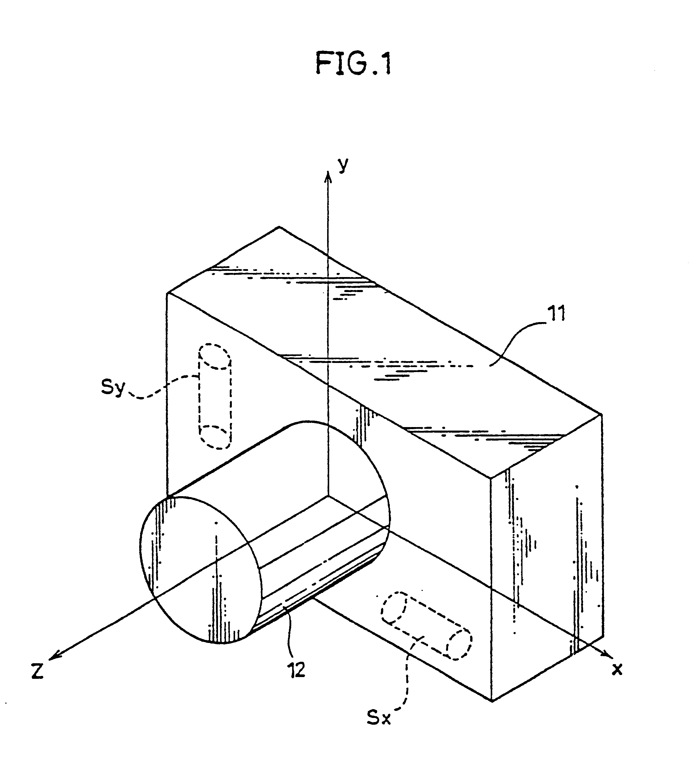
FIG. 1 is a perspective view conceptually showing the structure of a camera as one embodiment of the present invention. In a camera body 11, angular velocity sensors Sx and Sy for detecting angular velocities in a longitudinal shake direction and a lateral shake direction, respectively, are provided in a plane (the x-y plane in the figure) vertical to an optical axis (the z axis in the figure) of a taking lens 12.

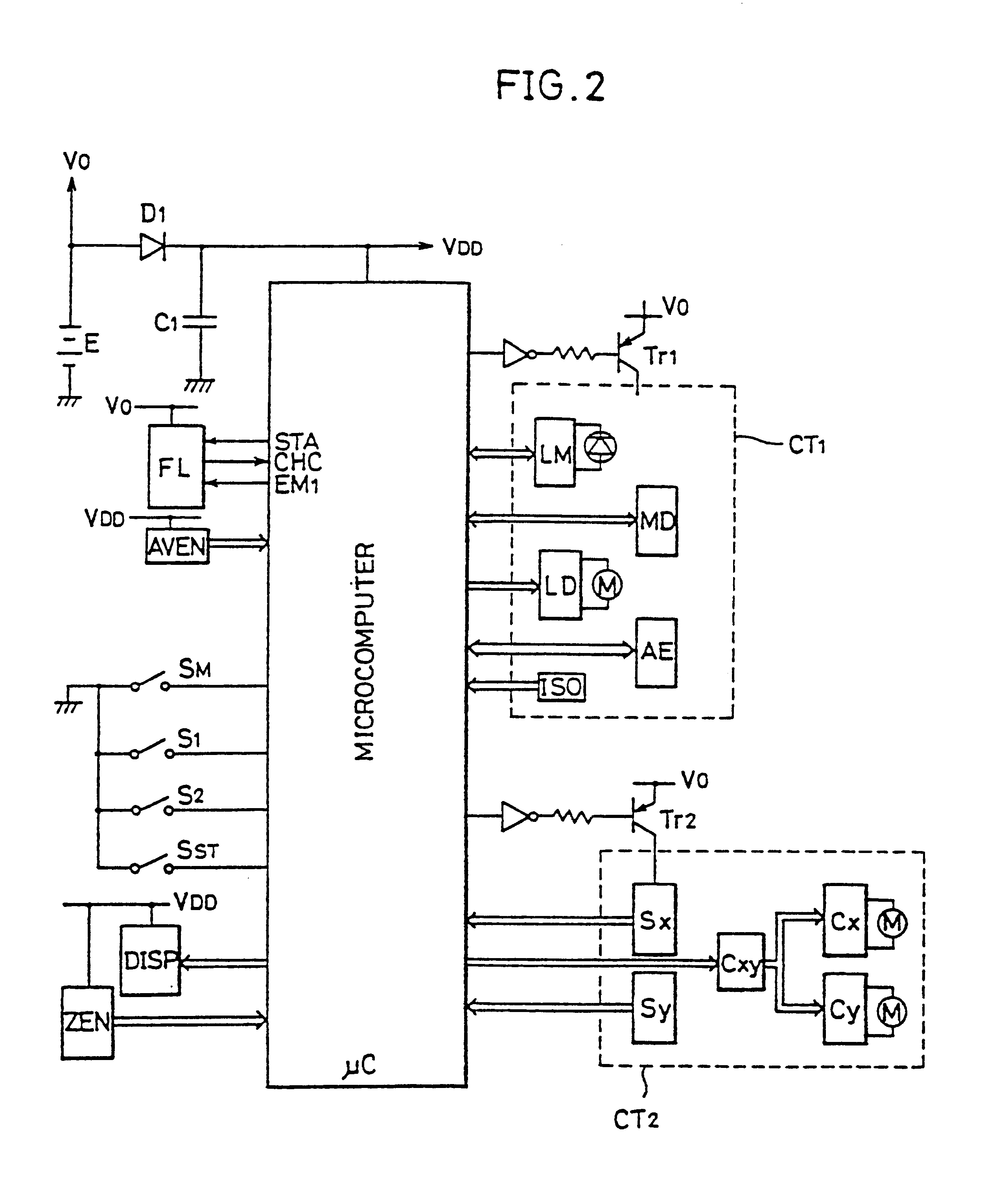
FIG. 2 is a block circuit diagram showing portions related to control of the camera shown in FIG. 1. Referring to FIG. 2, the camera according to the present invention includes a microcomputer .mu.C administrating sequence control of the entire camera, exposure calculation and exposure control. To the microcomputer .mu.C, peripheral circuits CT.sub.1 and CT.sub.2 which will be described in detail later, some switches for controlling operation of the camera, and a power source for supplying power to the microcomputer and the peripheral circuits CT.sub.1 and CT.sub.2 are conn...


PUM


Abstract

A camera capable of blurring correction includes an acceleration sensor detecting camera-shake amount, and a blurring correcting device correcting blurring of image on the basis of the sensor output. When a lens of the camera is driven for automatic focusing, the blurring is not corrected using an output of the acceleration sensor. Accordingly, blurring is not wrongly corrected.

Description

BACKGROUND OF THE INVENTIONField of the InventionThe present invention relates to cameras capable of correcting blurring occurring due to camera movement or camera-shake (hereinafter referred to as blurring), and particularly to cameras capable of blurring correction which can perform automatic focusing control (hereinafter referred to as AF).Description of the Related ArtCameras capable of correcting blurring have been proposed recently. As a camera-shake sensor in a camera capable of blurring correction, one which employs an angular velocity sensor is possible. The blurring correction is performed by detecting camera-shake amount of a camera employing an angular velocity sensor and driving a lens to correct it.Recent cameras have an AF function. In a camera having an AF function, a lens is automatically driven for focusing on an object. Then, acceleration noise is produced in the camera-shake detecting sensor due to vibration of the motor and vibration of the driving mechanism. It...

Claims


Application Information

Patent Timeline
IPC IPC(8): G03B5/00G03B17/00H04N5/232H04N5/235
CPCG03B5/00G03B17/00H04N5/23258H04N5/2327H04N5/23287H04N5/2353H04N5/23248G03B2205/0007G03B2217/005G03B2205/0053G03B2207/005H04N23/684H04N23/68H04N23/6812H04N23/687H04N23/73
Inventor HAMADA, MASATAKAOOTSUKA, HIROSHIMASUMOTO, HISAYUKITERAMOTO, TOUGO
Owner MINOLTA CO LTD
Why Eureka
Try Eureka