Method for reducing emissions from evaporative emissions control systems

a technology of evaporative emissions control and emission reduction, which is applied in the direction of combustion-air/fuel-air treatment, other chemical processes, separation processes, etc., can solve the problems of unacceptably high flow restriction of small particles, hinder the diffusional transport of vapors, and hydrocarbon air pollution, etc., to reduce diurnal breathing loss emissions, reduce emissions canisters, and reduce the effect of incremental capacity

Inactive Publication Date: 2005-10-25
INGEVITY SOUTH CAROLINA
View PDF47 Cites 69 Cited by
  • Summary
  • Abstract
  • Description
  • Claims
  • Application Information

AI Technical Summary

Benefits of technology

[0016]An invention is disclosed for sharply reducing diurnal breathing loss emissions from evaporative emissions canisters by the use of multiple layers, or stages, of adsorbents. On the fuel source-side of the canister, standard high working capacity carbons are preferred. On the vent-side, the preferred adsorbent volume exhibits a flat or flattened adsorbent isotherm on a volumetric basis in addition to certain characteristically desirable adsorptive properties across broad vapor concentrations, specifically relatively low incremental capacity at high concentration vapors compared with the fuel source-side adsorbent volume. Two approaches are described for attaining the preferred properties for the vent-side adsorbent volume. One approach is to use a filler and / or bed voidages as a volumetric diluent for flattening an isotherm. A second approach is to employ an adsorbent with the desired isotherm properties and to process it into an appropriate shape or form without necessarily requiring any special provision for dilution. Both such approaches provide a substantially lower emissions canister system without a significant loss in working capacity or an increase in flow restriction compared with prior art adsorbents used for automotive emissions control.

Problems solved by technology

Evaporation of gasoline from motor vehicle fuel systems is a major potential source of hydrocarbon air pollution.
It has been found that somewhat larger sizes hinder diffusional transport of vapors into and out of the carbon particle during dynamic adsorb and purge cycles.
On the other hand, somewhat smaller size particles have unacceptably high flow restriction for displaced air and hydrocarbon vapors during refueling.
While standard carbons used in the commercial canisters excel in terms of working capacity, these carbons are unable to meet DBL emission targets under normal canister operation.
Furthermore, none of the standard measures of working capacity properties correlate with DBL emission performance.
This strategy, however, has the drawback of complicating management of the fuel / air mixture to the engine during purge regeneration and tends to adversely affect tailpipe emissions, i.e., moving or redefining the problem rather than solving it.
The drawback is that there is a useful limit to which a portion of the bed can be elongated at reduced cross-sectional area without otherwise incurring excessive flow restriction by the canister system.
In practice, this limit does not allow employing a sufficiently narrowed and elongated geometry to meet emission targets.
However, this increases the complexity of control system management, and there appears some inherent safety concerns in providing heating internal of a canister for trapping fuel vapors.

Method used


Image

  • Method for reducing emissions from evaporative emissions control systems
  • Method for reducing emissions from evaporative emissions control systems
  • Method for reducing emissions from evaporative emissions control systems

Examples


Embodiment Construction

)

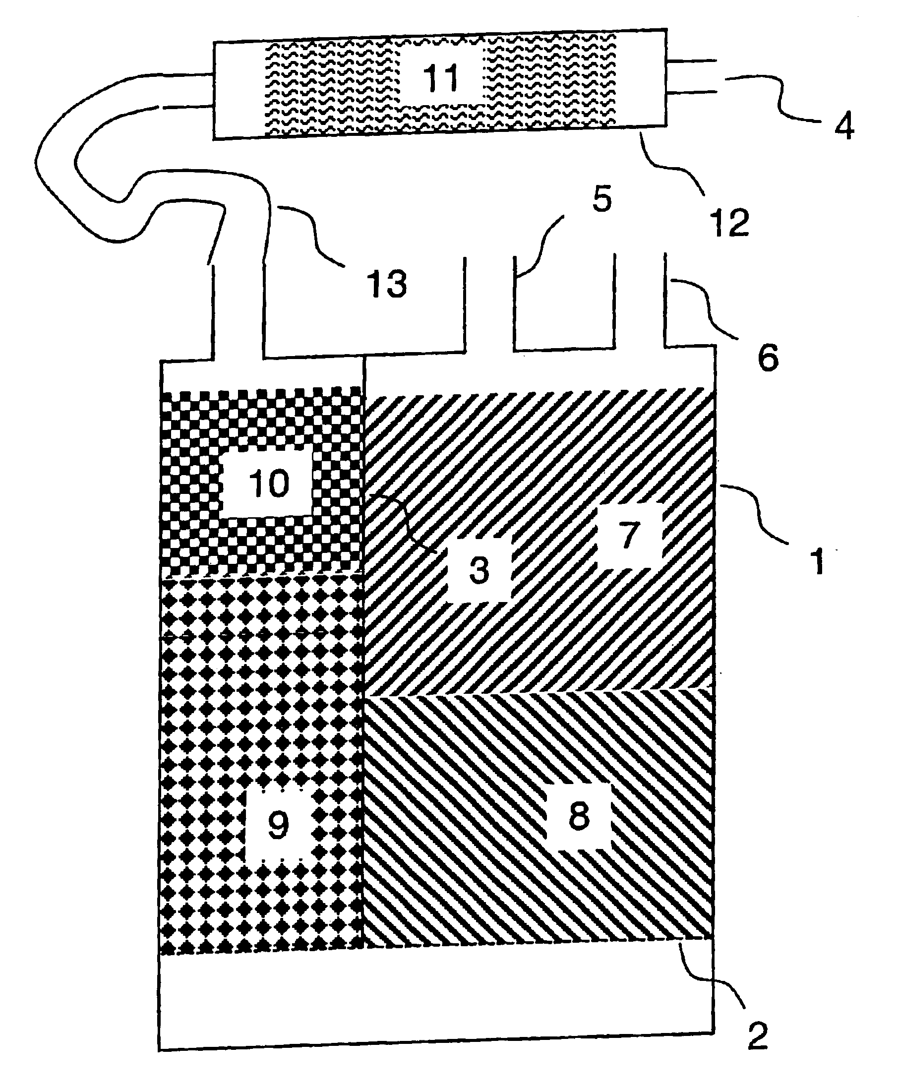
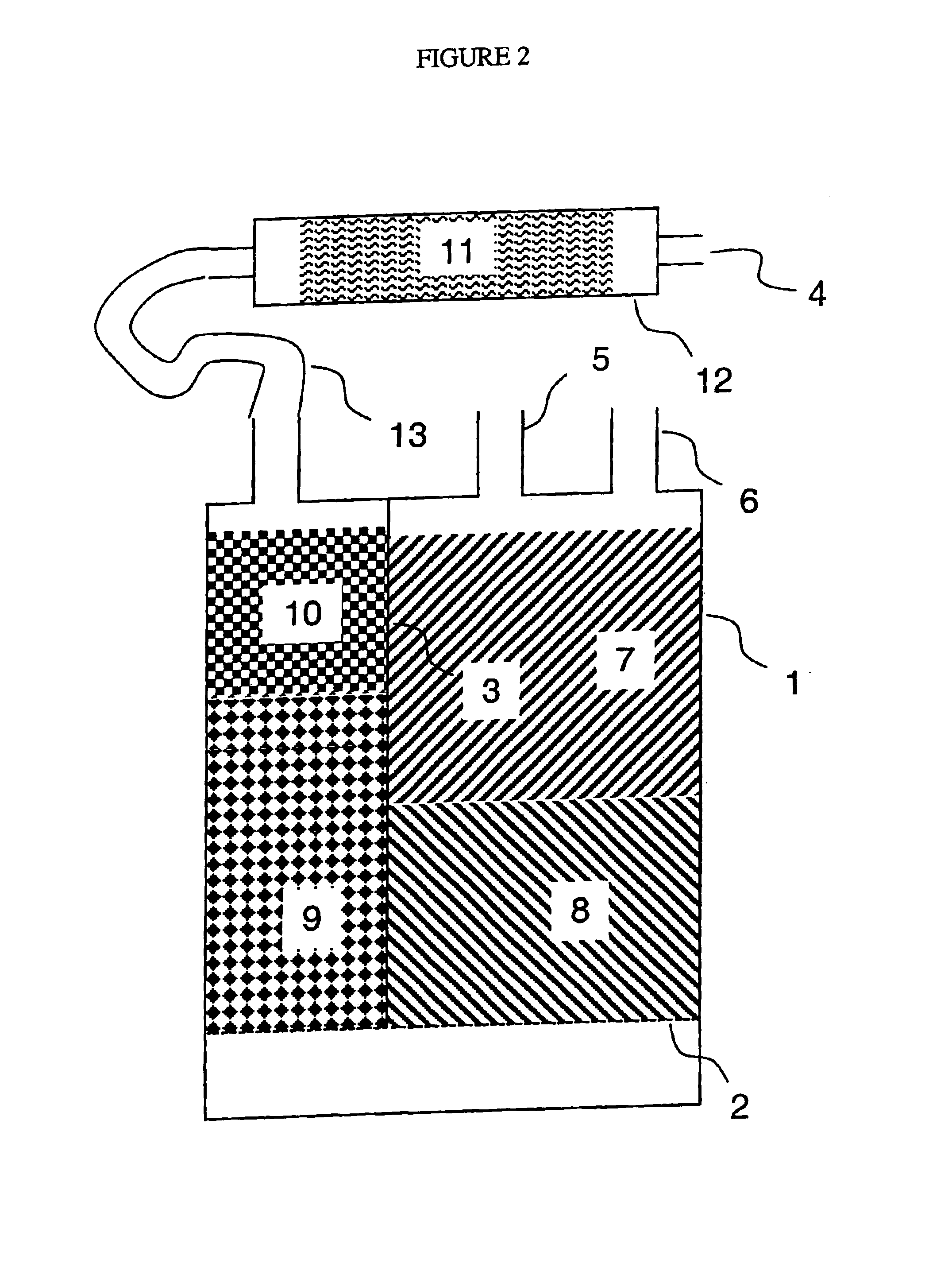
[0020]The disclosed invention relates to the use of multiple beds (or layers, stages, or chambers) of adsorbent materials, which, in combination, significantly reduce DBL emissions while maintaining the high working capacity and low flow restriction properties of the canister system. (See FIG. 2.) These adsorbents include activated carbon from a variety of raw materials, including wood, peat, coal, coconut, synthetic or natural polymer, and a variety of processes, including chemical and / or thermal activation, as well as inorganic adsorbents, including molecular sieves, porous alumina, pillared clays, zeolites, and porous silica, and organic adsorbents, including porous polymers. The adsorbents may be in granular, spherical, or pelletized cylindrical shapes, or may be extruded into special thin-walled cross-sectional shapes, such as hollow-cylinder, star, twisted spiral, asterisk, configured ribbons, or other shapes within the technical capabilities of the art. In shaping, inorganic...


PUM

PropertyMeasurementUnit
diameteraaaaaaaaaa
adsorption capacityaaaaaaaaaa
concentrationsaaaaaaaaaa

Abstract

Disclosed is a method for sharply reducing diurnal breathing loss emissions from automotive evaporative emissions control systems by providing multiple layers, or stages, of adsorbents. On the fuel source-side of an emissions control system canister, high working capacity carbons are preferred in a first canister (adsorb) region. In subsequent canister region(s) on the vent-side, the preferred adsorbent should exhibit a flat or flattened adsorption isotherm on a volumetric basis and relatively lower capacity for high concentration vapors as compared with the fuel source-side adsorbent. Multiple approaches are described for attaining the preferred properties for the vent-side canister region. One approach is to use a filler and / or voidages as a volumetric diluent for flattening an adsorption isotherm. Another approach is to employ an adsorbent with the desired adsorption isotherm properties and to process it into an appropriate shape or form without necessarily requiring any special provision for dilution. The improved combination of high working capacity carbons on the fuel source-side and preferred lower working capacity adsorbent on the vent-side provides substantially lower diurnal breathing emissions without a significant loss in working capacity or increase in flow restriction compared with known adsorbents used in canister configurations for automotive emissions control systems.

Description

[0001]This application claims the benefit of U.S. Provisional Application No. 60 / 335,897 filed on Nov. 21, 2001.BACKGROUND OF THE INVENTION[0002]1. Field of the Invention[0003]This invention relates to a method for reducing emissions from evaporative control systems including activated carbon particulate-filled canisters and adsorptive monolith-containing canisters, which monoliths include activated carbon, and to using said adsorbing canisters to remove volatile organic compounds, and other chemical agents from fluid streams. More particularly, this invention relates to using said vapor-adsorbing materials in hydrocarbon fuel consuming engines.[0004]2. Description of Related Art (Including Information Disclosed Under 37 CFR 1.97 and 37 CFR 1.98)[0005](a) Standard Working Capacity Adsorbents[0006]Evaporation of gasoline from motor vehicle fuel systems is a major potential source of hydrocarbon air pollution. The automotive industry is challenged to design engine components and syste...

Claims


Application Information

Patent Timeline
Patent Type & Authority Patents(United States)
IPC IPC(8): B01D53/04F02M25/08B01J20/18B01J20/20B01J20/28
CPCB01D53/02B01D2253/102B01D2253/104B01D2253/108B01D2253/11B01D2253/342B01D2259/4145B01D2259/4516F02M25/0854Y10S95/90B01D53/04F02M25/08
Inventor HILTZIK, LAURENCE H.JAQIELLO, JACEK Z.TOLLES, EDWARD DONWILLIAMS, ROGER S.
Owner INGEVITY SOUTH CAROLINA
Why Eureka
Try Eureka