Concrete panel construction

a technology of concrete panels and construction, applied in the direction of building components, discharging arrangements, feeding arrangments, etc., can solve the problems of difficult monitoring of accurate formulas on the building site, system encountering a large number of potential problems, and difficulty in ensuring the quality of mortar materials, etc., to achieve the effect of simple and efficien

Inactive Publication Date: 2006-05-09
STONETILE CANADA
View PDF3 Cites 56 Cited by
  • Summary
  • Abstract
  • Description
  • Claims
  • Application Information

AI Technical Summary

Benefits of technology

[0015]The object of the present invention is to solve the above mentioned problems by providing a relatively simple, efficient method and apparatus for producing concrete panels.

Problems solved by technology

Such systems often encounter a great number of potential problems related to the particular systems.
For example, the quality of the mortar materials is often impaired due to the fact that monitoring of accurate formulas on the building site is difficult.
Moreover, variations in weather and temperature can affect the mortars significantly.
The installation of typical masonry products is often hindered by weather conditions, such as rain and freezing conditions which usually force a work stoppage unless measures are taken to shield the work area.
The quality of these materials is further impaired due to the fact that typically these mortar materials are allowed to air dry without attempting to seal these cementitious products for proper curing.
Efflorescence is extremely difficult to prevent in presently known masonry cladding installation systems.
Often with stucco or artificial stone, an inferior cladding system is achieved due to the fact that no venting space is provided in behind the cladding.
Generally speaking all existing masonry cladding systems are plagued with cracking problems.
It is virtually impossible to prevent this condition.
Furthermore, all existing masonry cladding systems require unsightly expansion joints, both laterally and vertically.
Concealing these joints is virtually impossible.
It is also difficult to maintain a uniform minimum thickness with presently known masonry cladding systems.
This adds greatly to their expense.
Finally, known masonry cladding systems are prone to dirt entrapment.

Method used


Image

  • Concrete panel construction
  • Concrete panel construction
  • Concrete panel construction

Examples


Embodiment Construction

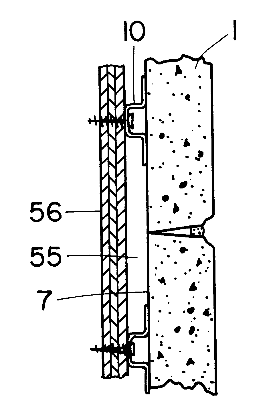
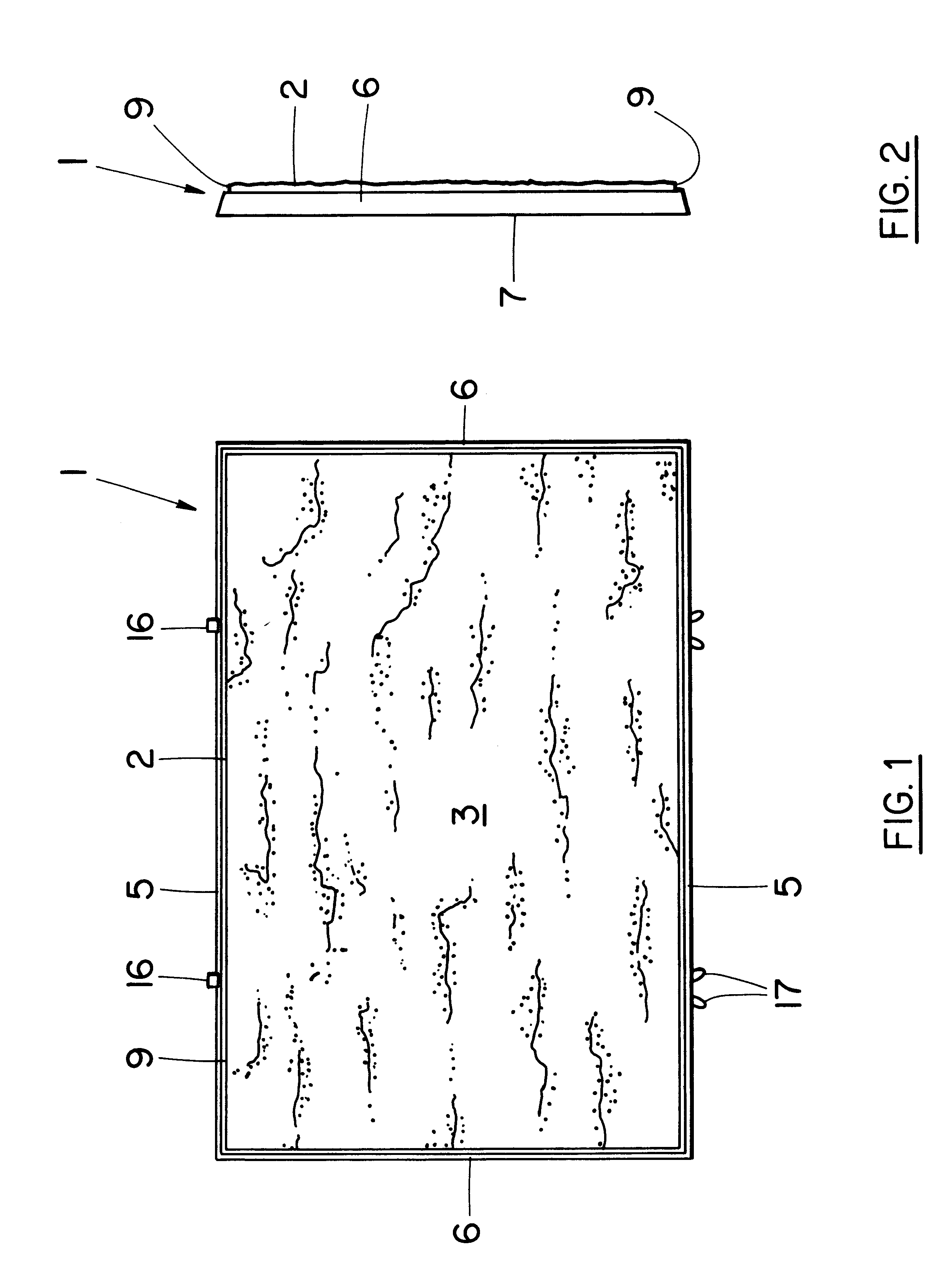
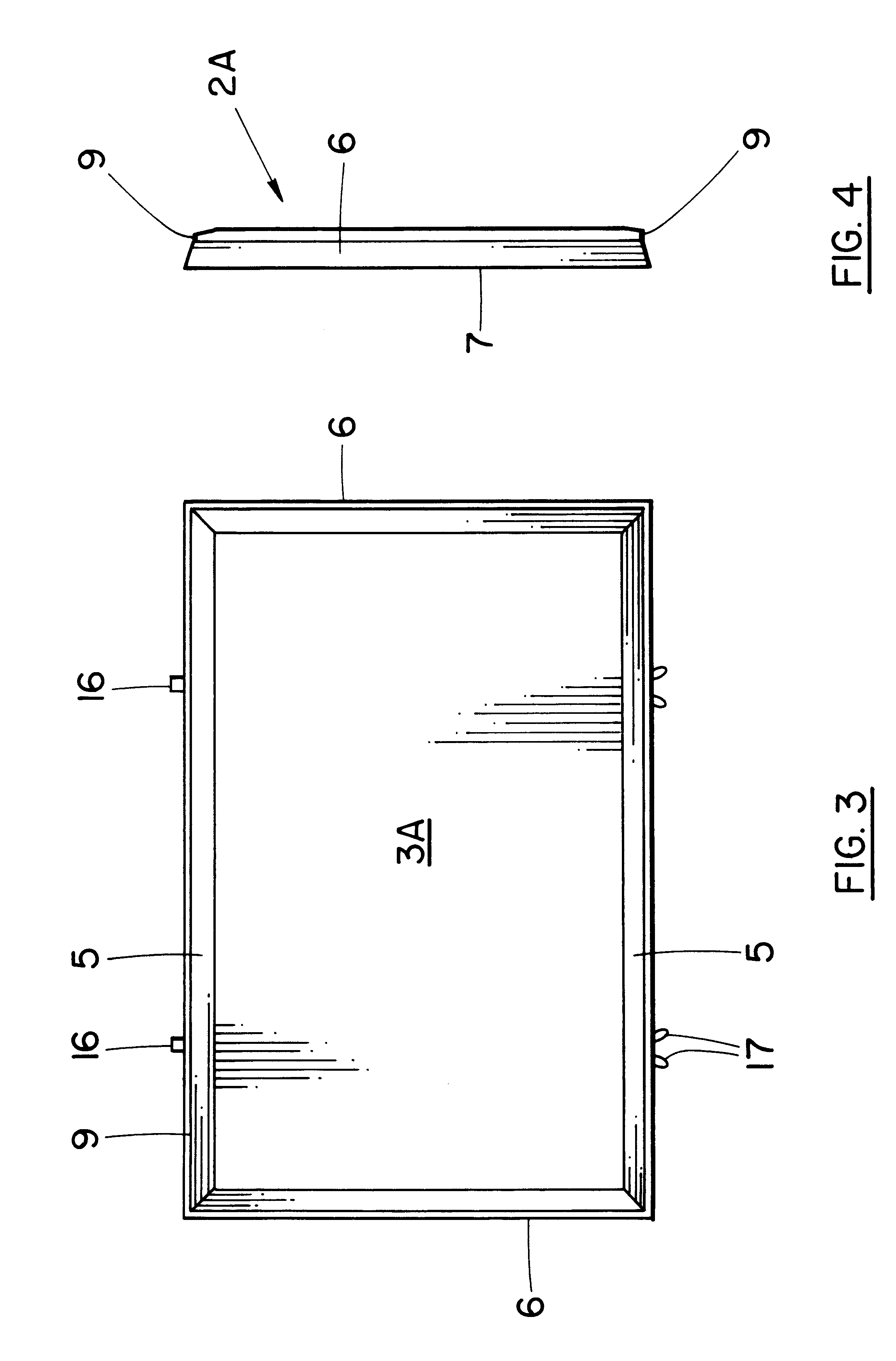
[0092]Referring to FIGS. 1 to 6, the method and apparatus of the present invention are designed to produce a concrete panel generally indicated at 1. The panel includes a thin rectangular body 2, typical dimensions of which are 12″×18″×⅝″, however, irregular shapes as shown in FIG. 5 may also be formed. The body 2 has a textured, beveled or irregular outer or front surface 3, sloping, tapered sides 5 and 6 and a rough, planar inner or rear surface 7. A groove 9 or caulking ledge extends around the side periphery of the panel 1. FIGS. 3 and 4 show a similar panel 1A to that of FIGS. 1 and 2 but with smooth face 3A &2A. A pair of hangers 10 are embedded in the rear surface 7 of the panel 1A. The hangers 10 (FIG. 6) are used to mount the panel 1 on plywood backing or other suitable backing shown in FIGS. 20 and 21 when finishing a wall. A flexible grout is provided between the panels to complete the exterior wall.

[0093]As shown in FIGS. 7 to 10, each hanger 10 includes an elongated, ga...


PUM

PropertyMeasurementUnit
angleaaaaaaaaaa
angleaaaaaaaaaa
angleaaaaaaaaaa

Abstract

A concrete panel system comprising a plurality of concrete panels arranged in side-by-side fashion on a substantially vertical supporting wall, each of the panels comprising a rectangular body having a front surface and a rear surface and beveled side edges, the side edges each forming an angle of between eighty-five and ninety degrees with the rear surface, and a concave caulking groove lying between and connecting each of the beveled side edges with the front face, the side edges of adjacent panels forming a V-joint between the adjacent panels, a flexible sealant material in a portion of the caulking grooves of adjacent panels and a portion of the V-joint for providing a seal between adjacent panels, and a hanger element embedded in the rear of the panels for securing the panels to the supporting wall.

Description

[0001]This application is a continuation-in-part of U.S. application Ser. No. 08 / 603,243, filed Feb. 20, 1996 now abandoned.[0002]This invention relates to an improved building panel, as well as a method and apparatus for producing the building panels, and in particular to concrete building panels for exterior use on buildings. This new cladding system is a radical departure from any commonly used systems.FIELD OF THE INVENTION[0003]Thin panels of the type produced in accordance with the present invention are used to simulate natural stones. Because the panels are relatively thin, the cost of producing a simulated stone finish is substantially less expensive than when using artificial or real stones. Panels of the type described herein are typically produced in separate molds which is both time consuming and expensive.BACKGROUND OF THE INVENTION[0004]Cladding systems such as stucco, brick, stone and artificial stone veneer are typically manufactured off-site and installed on a build...

Claims


Application Information

Patent Timeline
Patent Type & Authority Patents(United States)
IPC IPC(8): E04B2/28B28B1/087B28B13/02B28B13/06B28B23/00E04F13/08E04F13/14
CPCB28B1/0873B28B13/0215B28B13/06B28B23/0056E04F13/0803E04F13/141
Inventor KUELKER, PETER A.
Owner STONETILE CANADA
Why Eureka
Try Eureka