Optical channel regulator and method

a technology of optical channel and regulator, applied in the field of optical channel regulator and method, can solve the problems of channel imbalance, signal inequalities, and the loss of optical amplifiers used in multiple channel wavelength division multiplexed communication systems, and achieve the effect of reducing disadvantages and problems associated with the use of multiplexed optical amplifiers

Inactive Publication Date: 2006-11-07
RPX CORP +1
View PDF13 Cites 6 Cited by
  • Summary
  • Abstract
  • Description
  • Claims
  • Application Information

AI Technical Summary

Benefits of technology

[0007]The present invention provides an optical channel regulator method that substantially eliminates or reduces disadvantages and problems associated with previously developed optical channel regulation schemes.

Problems solved by technology

Another problem faced is that optical amplifiers used in multiple channel wavelength division multiplexed communication systems often do not have uniform gain across all of the optical channels.
This creates some channel imbalance.
In other systems where optical amplifiers are used as repeaters, the cascade of the amplifiers results in signal inequalities even when they are well balanced at the head end.
Other problems relate to the configuration of a bi-directional line amplifier (BDLA) which uses a single amplifier.
Further, significant power level imbalances between channels at the end of a cascade of amplifiers may require attenuation of the strong channels to keep the signal level to the receiver at an acceptable level.
However, the selection or the adjustment of the attenuators requires manual measurement of each optical channel, since the source transmitter power level for each channel varies and is not precisely known beforehand.
Furthermore, when the source transmit power changes, due to aging or module replacement, the attenuator adjustment process has to be repeated.

Method used


Image

  • Optical channel regulator and method
  • Optical channel regulator and method
  • Optical channel regulator and method

Examples


Embodiment Construction

[0019]Preferred embodiments of the present invention are illustrated in the FIGURES, like numerals being used to refer to like and corresponding parts of the various drawings.

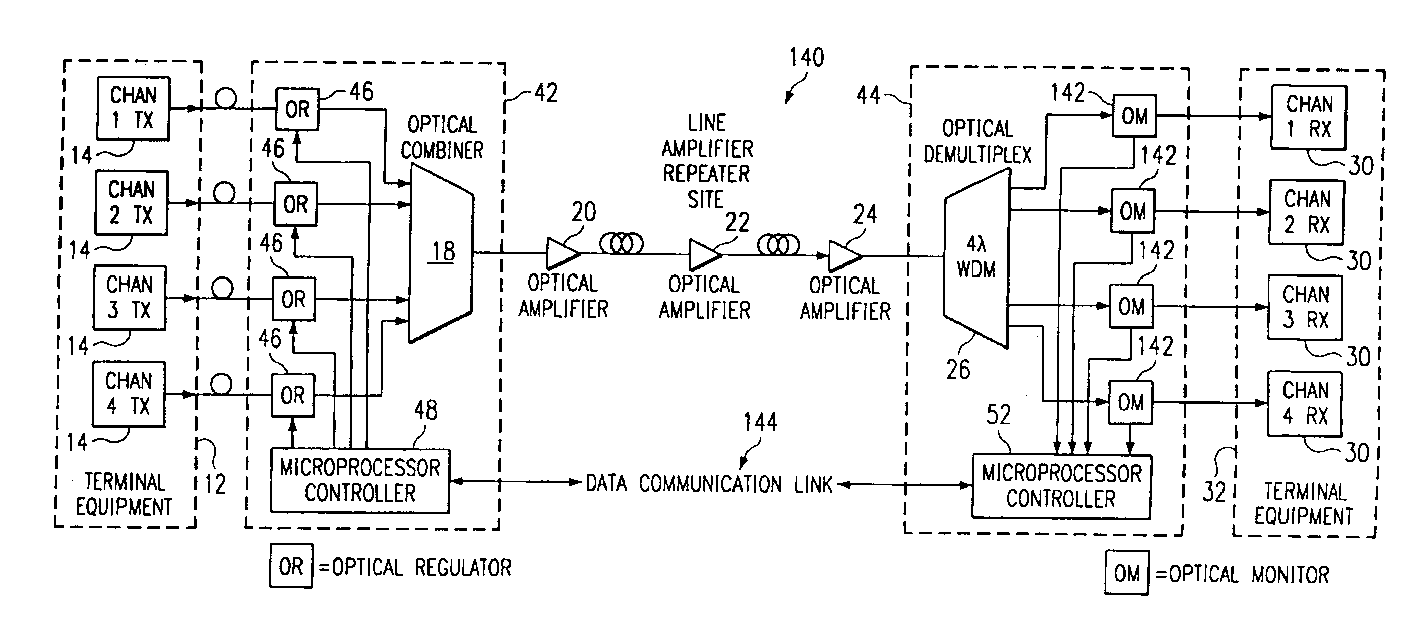
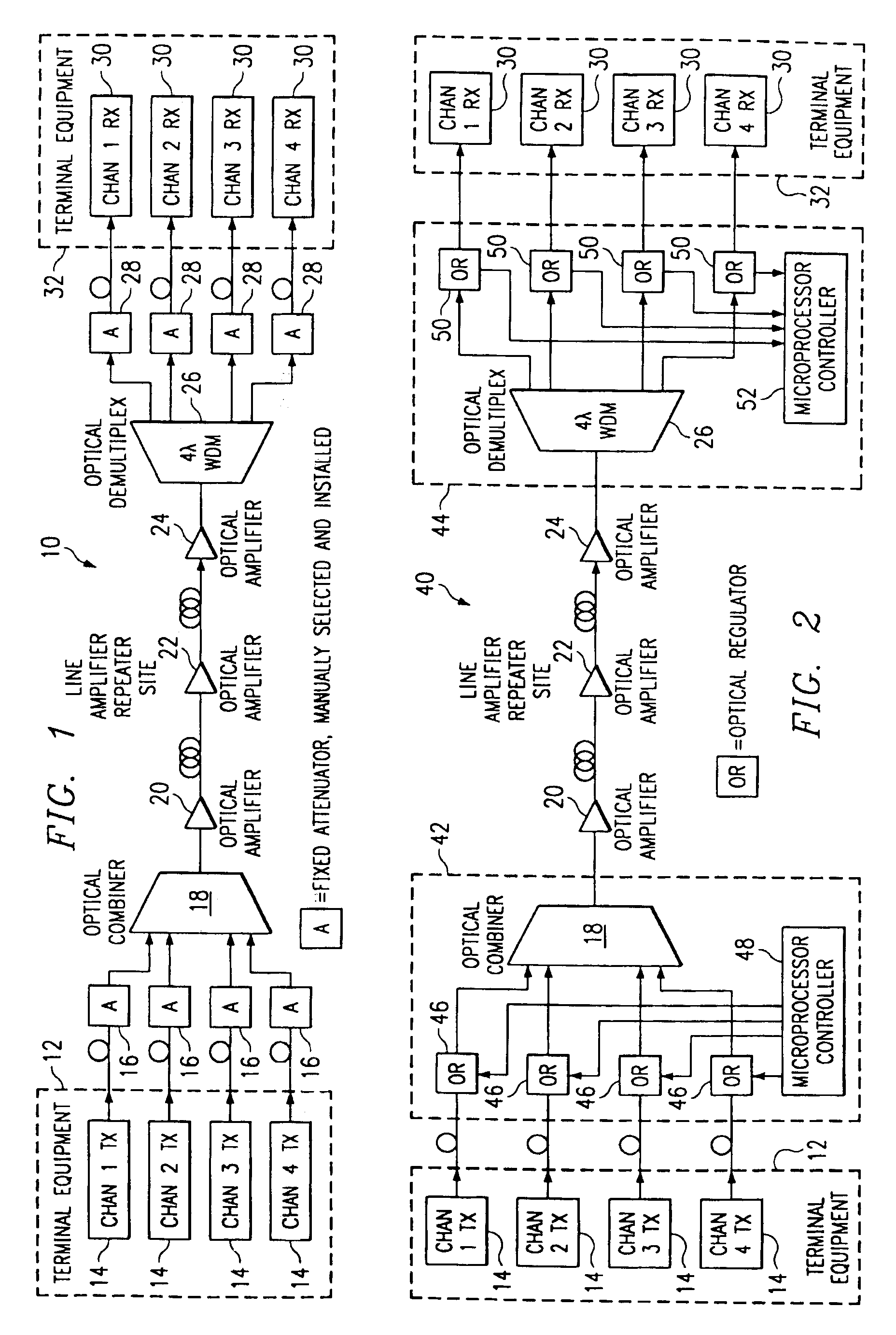
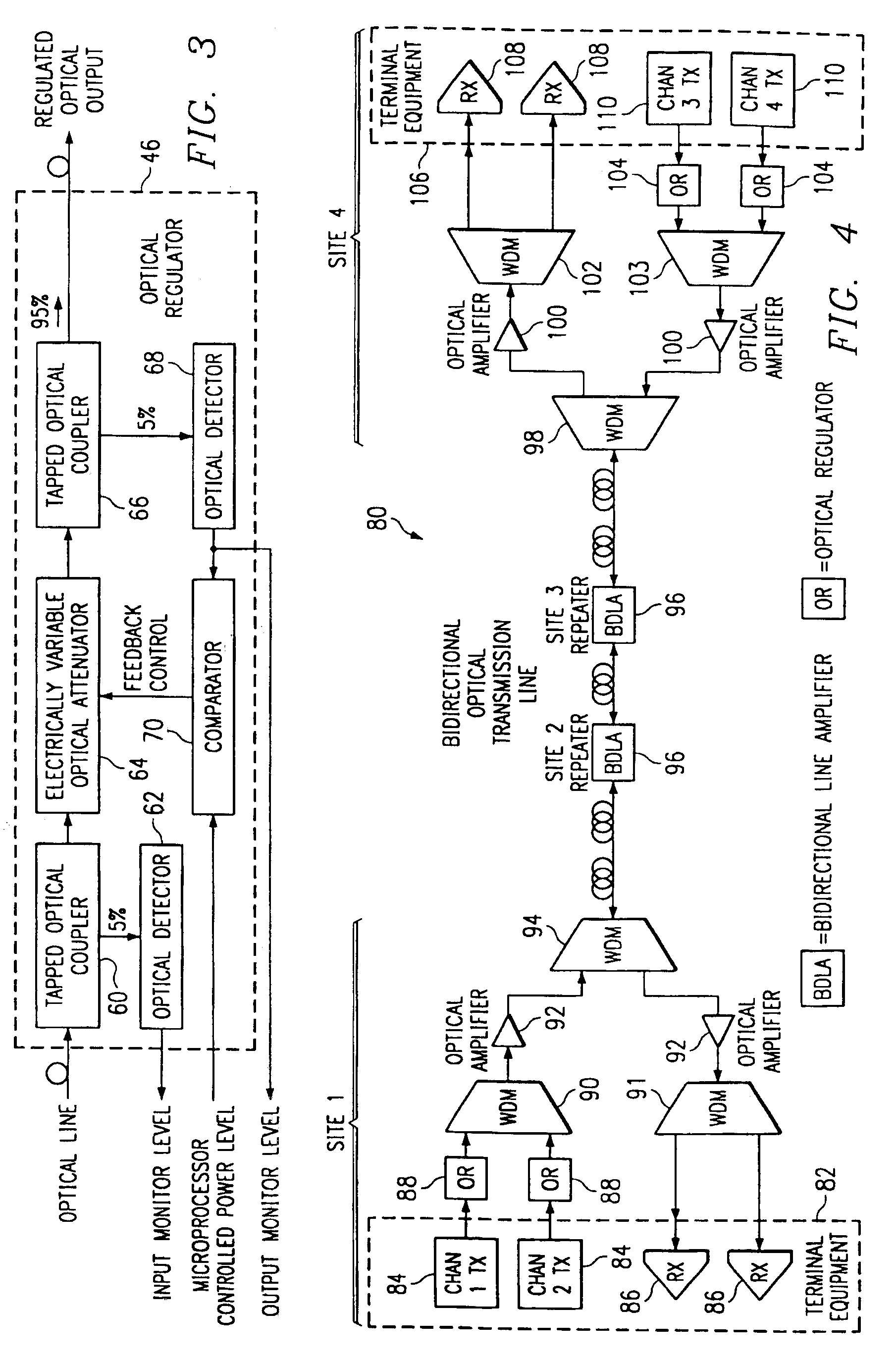
[0020]The optical channel regulator of the present invention electronically performs a power level measurement for each channel of a wavelength division multiplexed communication system. The optical channel regulator of the present invention also electronically varies the path attenuation to bring all optical channels into balance before being combined in a multiplexer and before being amplified. If the balance changes at a later time, the control system automatically readjusts to maintain the balance.

[0021]More specifically, the present invention provides a method for regulating an optical channel. The optical channel regulator includes an electrically variable optical attenuator receiving an optical signal. The attenuator attenuates the optical signal responsive to a feedback control signal and yields an atte...


PUM


Abstract

An optical channel regulator (46) is provided. The optical channel regulator (46) includes a tapped optical coupler (60) receiving an optical line carrying an optical signal. The tapped optical coupler (60) provides substantially all of the optical signal as an output. An electrically variable optical attenuator (64) receives the output of the tapped optical coupler (60) and attenuates the optical signal responsive to a feedback control signal. A second tapped optical coupler (66) receives an output of the attenuator (64). The second coupler (66) provides substantially all of the received optical signal as an output and provides a remaining portion of the optical signal as a tapped output. An optical detector (68) then receives the tapped output and provides an output signal representing the optical signal. A comparator (70) receives the output signal of the optical detector (68) and a reference signal. The comparator (70) compares the output signal and the reference signal and provides the feedback control signal to the attenuator (64) responsive to the comparison. As part of a multi-channel communication system, the regulator is used to adjust the levels of each channel for automatically maintaining channel balance and equalization.

Description

[0001]This application claims priority under 35 U.S.C. 119(e) to Provisional Application No. 60 / 060,526 filed Sep. 30, 1997.<?insert-end id="INS-S-00001" ?>TECHNICAL FIELD OF THE INVENTION[0002]This invention relates in general to optical communication systems, and more particularly to an optical channel regulator and method.BACKGROUND OF THE INVENTION[0003]In multiple channel wavelength division multiplexed (WDM) communication systems, optical amplifiers are used to boost signal powers to provide for longer transmission spans. When using optical amplifiers in such systems, it is important to balance the channels at the input to the amplifiers to assure that the available amplifier output power is shared equally among the channels. If the channels are not balanced across each amplifier input, the weaker signals reduce the transmission span distance.[0004]Another problem faced is that optical amplifiers used in multiple channel wavelength division multiplexed communication syst...

Claims


Application Information

Patent Timeline
Patent Type & Authority Patents(United States)
IPC IPC(8): H04J14/02H04B10/18H04B10/17
CPCH04B10/25073H04B10/2971H04J14/0221
Inventor DUGAN, J. MICHAELMAXHAM, KENNETH Y.
Owner RPX CORP
Why Eureka
Try Eureka