
Variable speed drive chiller system

a chiller system and variable speed technology, applied in the field of variable speed drive chiller systems, can solve the problems of adding a variable speed drive to a conventional compressor, greatly increasing the cost, and adding a degree of redundancy, so as to minimize the initial cost and minimize the operating cost

Inactive Publication Date: 2007-05-01
CARRIER CORP
View PDF75 Cites 31 Cited by
  • Summary
  • Abstract
  • Description
  • Claims
  • Application Information

AI Technical Summary

Benefits of technology

[0003]The cost of a variable speed drive is on the order of that of a compressor. So, adding a variable speed drive to a conventional compressor greatly increases the cost and adds a degree of redundancy since the unloader valve, or other mechanical unloading structure, has some functional overlap with the variable speed drive in that both can control compressor capacity. While the variable speed drive is external to the compressor, an unloader valve is internal to the compressor. Being internal to the compressor, the unloader valve requires additional manufacturing steps to accommodate it in the compressor. Specifically, the unloader valve is located in a cusp and effectively forms a portion of the bores. This requires precision machining to achieve the requisite sealing with the rotors and introduces a leakage path along the interface of the unloader valve with the rotor bores. Other types of mechanical unloaders such as poppets also require additional manufacturing steps in order to be accommodated in a compressor.
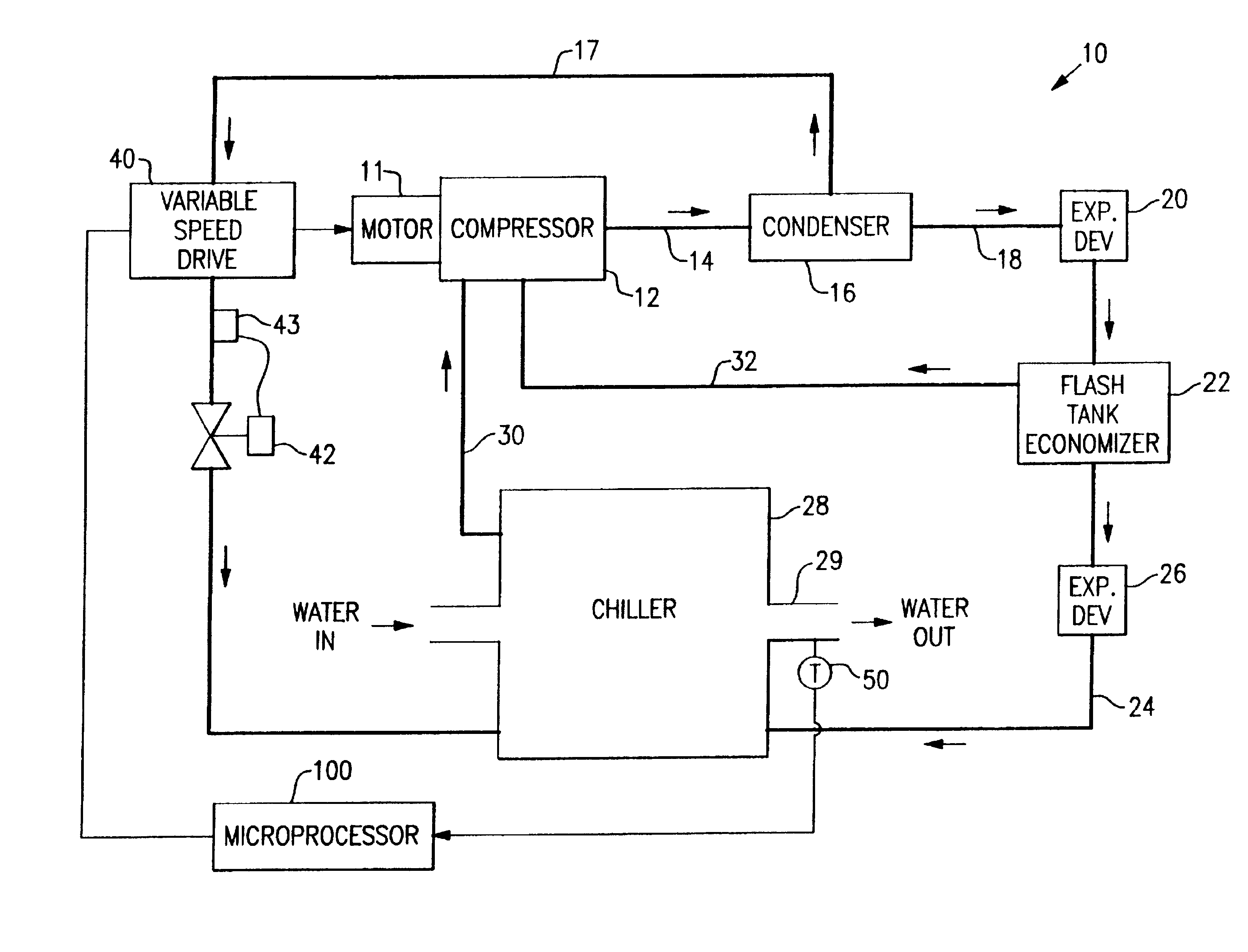
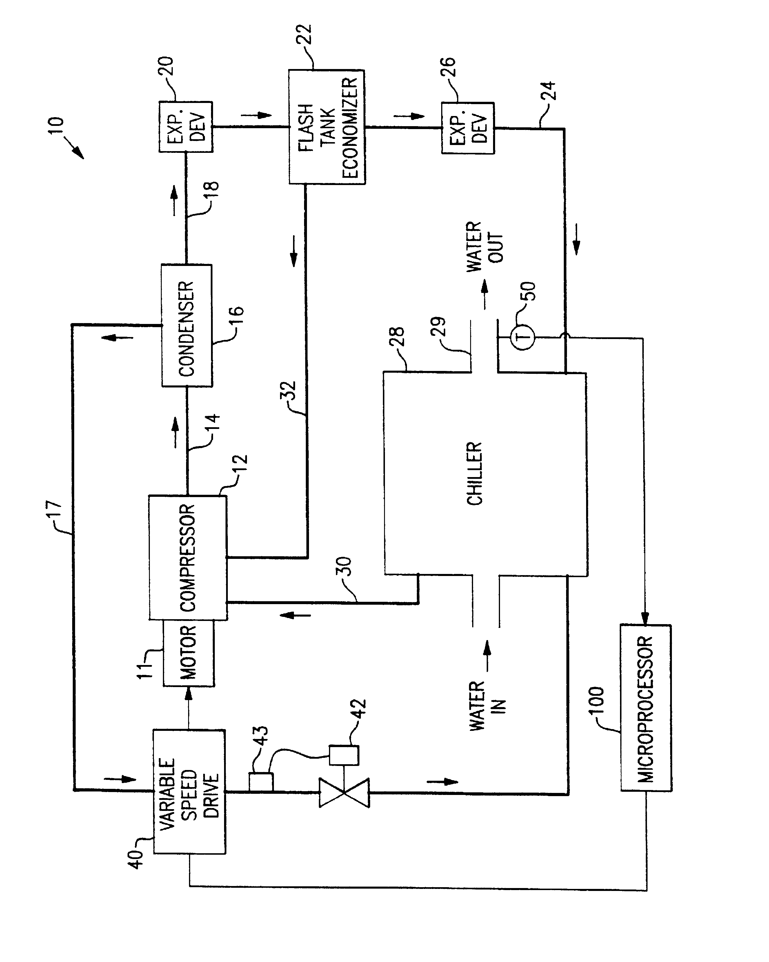
[0004]The present invention eliminates the mechanical unloader structure and thereby simplifies the manufacture of the compressor while reducing costs. All of the control of the compressor is through the variable speed drive so that further efficiency increases and cost reductions can be achieved by properly selecting the variable speed drive, motor, compressor and chiller for a particular application. The required drive amperage of the variable speed drive, and also its cost, is directly related to the chiller performance and to the motor power factor. Improvements in the chiller performance and motor power factor lowers the average cost of a variable speed drive for an application.
[0005]In the case of the compressor, considerations for unloading include the amperage or load requirements over the range of operation, efficiency over the range of operation and the minimum speed requirements for bearing life which is dependent upon lubrication circulation with the refrigerant. The motor must be matched with both the variable speed drive and the compressor in order to optimize the speed of the compressor. For example, the ideal compressor speed for a given load is not usually the same as the synchronous speed. Also, the variable speed drive may be required to compensate for the various input frequencies and voltages used around the world and one motor voltage can be used for all applications over a range of supply voltages. For example, one variable speed drive and motor combination might be efficiently used for power supplied at 50 Hz or 60 Hz and over a voltage range of 346 volts to 480 volts since the variable speed drive output would remain the same. The system current usage can be minimized through a unity, or approaching unity, input power factor of the variable speed drive. The variable speed drive output can be increased by using system refrigerant for cooling such as is taught in commonly assigned U.S. Pat. No. 6,116,040. This permits the use of a smaller and therefore less expensive variable speed drive to produce a desired output.
[0008]It is another object of this invention to reduce the initial cost of a refrigeration system employing a variable speed drive.
[0011]Basically, the compressor in a refrigeration system is controlled solely by a variable speed drive which controls the motor of the compressor by virtue of the varying of the frequency of the electric current provided to the motor. To minimize the initial cost and to minimize operating costs, the variable speed drive is cooled by refrigerant from the refrigeration system which permits the use of a smaller drive, and the variable speed drive is operated at, or approaching, a unity power factor.

Problems solved by technology

So, adding a variable speed drive to a conventional compressor greatly increases the cost and adds a degree of redundancy since the unloader valve, or other mechanical unloading structure, has some functional overlap with the variable speed drive in that both can control compressor capacity.
The required drive amperage of the variable speed drive, and also its cost, is directly related to the chiller performance and to the motor power factor.

Method used


Image

  • Variable speed drive chiller system
  • Variable speed drive chiller system

Examples


Embodiment Construction

[0014]For a refrigeration system a particular system capacity is the starting point in designing the system. A compressor capable of producing the required capacity will be chosen based upon factors such as cost, efficiency and operating speed. The selection of the compressor will be in conjunction with the selection of the motor. Motors are available having power factors in the range of 0.80 to 0.93 and the motor will be selected based upon cost, power factor, efficiency at design compressor speed. Variable speed drives are available which have power factors running from 0.99 to unity. However, the differences between the standard sizes of the variable speed drives are relatively large such that a considerably oversized variable speed drive might be the smallest standard drive available sufficient to meet design requirements. By cooling the variable speed drive with refrigerant from the condenser, it may be operated at higher than its air cooled drive design capacity because of the...


PUM


Abstract

The compressor in a refrigeration system is controlled solely by a variable speed drive which controls the motor of the compressor by virtue of the varying of the frequency of the electricity provided to the motor. To minimize the initial cost and to minimize operating costs, the variable speed drive is cooled by refrigerant from the refrigeration system which permits the use of a smaller drive, and the variable speed drive is operated at, or approaching, a unity power factor.

Description

[0001]A second reissue application, 11 / 397,888, for U.S. Pat. No. 6,434,960, has been filed on Apr. 4, 2006.BACKGROUND OF THE INVENTION[0002]In screw compressors the bores for the rotors overlap. The overlapping bores create cusps in the nature of the waist of a figure eight. One of the cusps in the normal lactation for one form of a mechanical unloader which forms a portion of the bore and coacts with the rotors as it moves axially in the cusp to unload and to control the V1 or discharge volume to suction volume ratio, of the compressor. The unloader is normally driven by a solenoid. To provide a greater degree of control, it is common to provide a variable speed drive which controls the motor by changing the frequency of the electric power being supplied to the motor by the variable speed drive.SUMMARY OF THE INVENTION[0003]The cost of a variable speed drive is on the order of that of a compressor. So, adding a variable speed drive to a conventional compressor greatly increases th...

Claims


Application Information

Patent Timeline
IPC IPC(8): F25B49/00F25B1/00F25B27/00F25B1/047F25B31/00F25B49/02
CPCF25B1/047F25B31/006F25B49/025F25B2400/13F25B2400/23F25B2600/024F25B2600/0253F25B2700/21173Y02B30/70A01K61/51
Inventor ROUSSEAU, WILLIAM H.
Owner CARRIER CORP
Learn More