System for coupling programmable logic device to external circuitry which selects a logic standard and uses buffers to modify output and input signals accordingly

Inactive Publication Date: 2008-01-22
ALTERA CORP
View PDF73 Cites 0 Cited by
  • Summary
  • Abstract
  • Description
  • Claims
  • Application Information

AI Technical Summary

Problems solved by technology

One deficiency of conventional PLDs and their I / O circuitry is that each PLD must be configured to operate with specific external circuitry.
This deficiency is even more apparent in view of the programmable nature of PLDs and the flexibility provided to the end users.
Further, the nature of PLDs, as semiconductor devices, is that they are susceptible to a wide range of potential hazards, such as electrostatic discharge (ESD).
One deficiency of Gunning and other known driver circuitry is the limited scope with which the circuitry may be used.

Method used


Image

  • System for coupling programmable logic device to external circuitry which selects a logic standard and uses buffers to modify output and input signals accordingly
  • System for coupling programmable logic device to external circuitry which selects a logic standard and uses buffers to modify output and input signals accordingly
  • System for coupling programmable logic device to external circuitry which selects a logic standard and uses buffers to modify output and input signals accordingly

Examples


Embodiment Construction

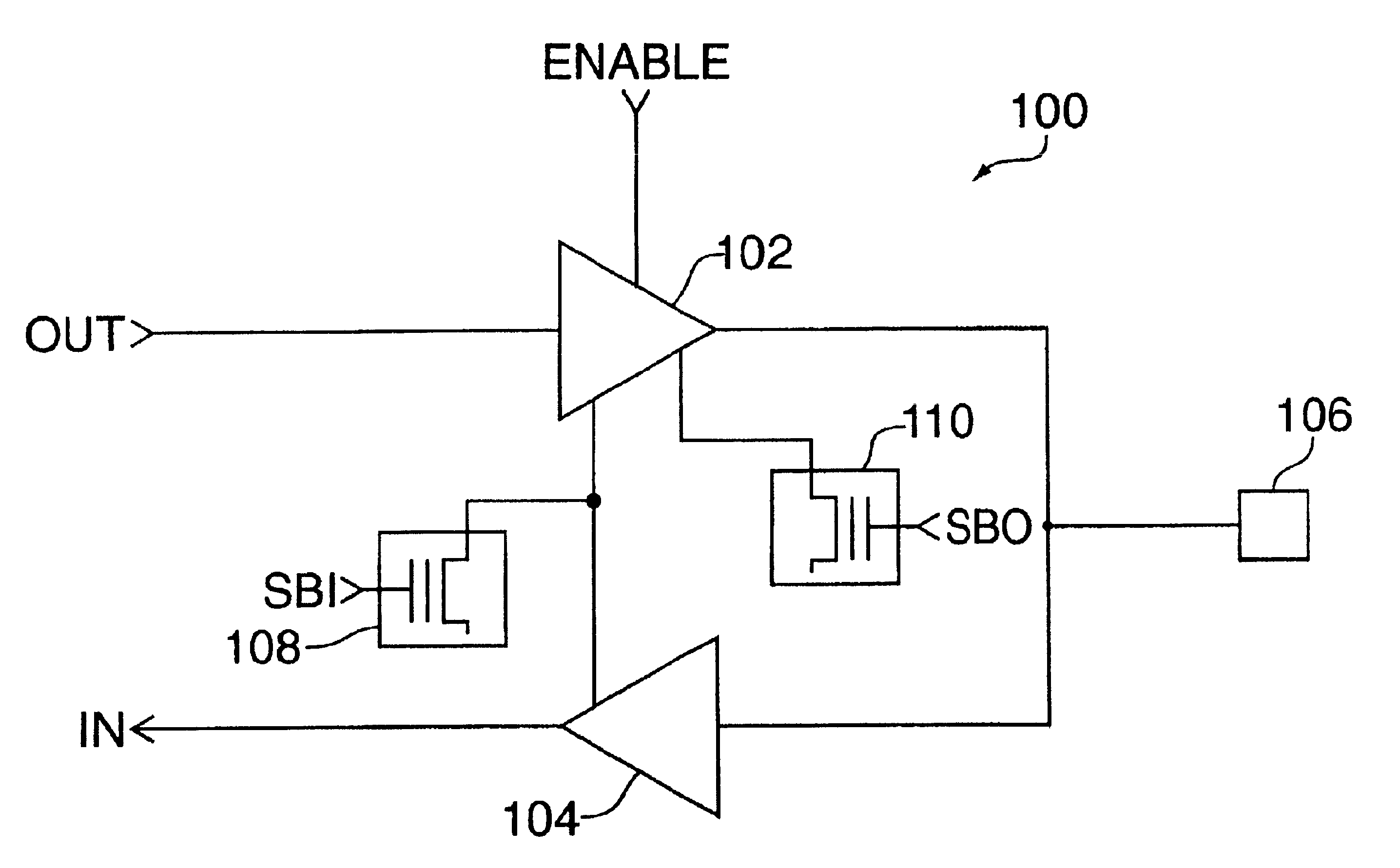
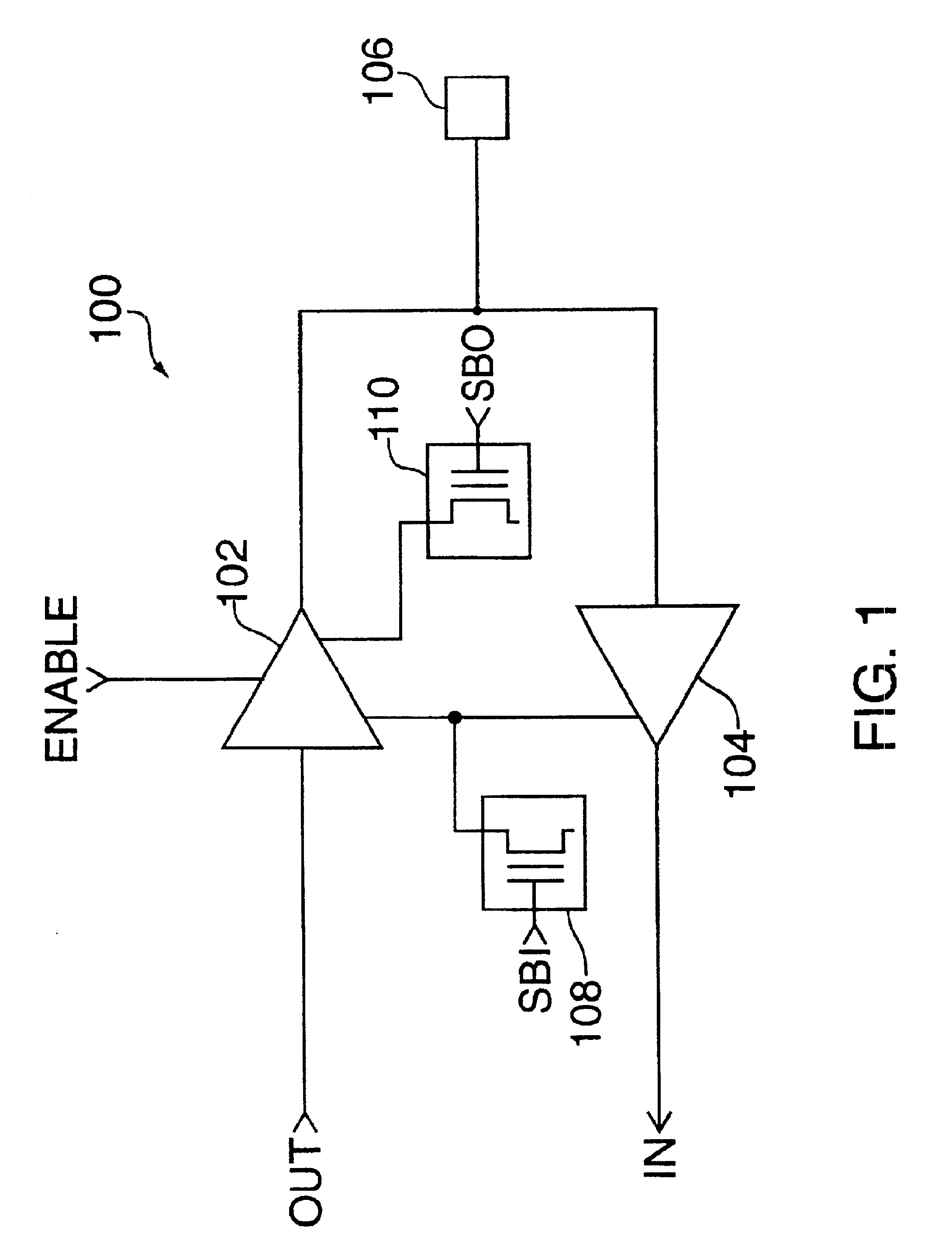
[0022]FIG. 1 shows a schematic block diagram of a programmable input / output (I / O) circuit 100 which incorporates principles of the present invention. I / O circuit 100 includes output driver 102, input driver 104, I / O pad 106, and programmable elements 108 and 110. Output driver 102, which has an input terminal to receive output signals from a programmable logic device (PLD) (not shown), provides an output signal (OUT) to I / O pad 106 at an appropriate voltage level that corresponds to a selected logic standard. Additionally, output driver 102 has three control lines which receive signals ENABLE, SB0 (Select Bit 0), and SB1 (Select Bit 1).

[0023]Input driver 104, which has an input terminal to receive signals from I / O pad 106 and output buffer 102, provides input signals to the PLD at the appropriate level of voltage, regardless of the voltage level of the signal receive on the input terminal. In addition, input driver 104 also receives control signal SB1 from programmable element 108. ...


PUM


Abstract

A programmable input / output device for use with a programmable logic device (PLD) is presented comprising an input buffer, an output buffer and programmable elements. The programmable elements may be programmed to select a logic standard for the input / output device to operate at. For instance, a given set of Select Bits applied to the programmable elements may select TTL logic, in which case the input and output buffers would operate according to the voltage levels appropriate for TTL logic (e.g., 0.4 volts to 2.4 volts). For a different set of Select Bits, the GTL logic standard would be applied (e.g., 0.8 volts to 1.2 volts). The invention enables a single PLD to be used in conjunction with various types of external circuitry.

Description

BACKGROUND OF THE INVENTION[0001]This invention relates to programmable logic devices (“PLDs”), and more particularly to a new architecture for the input / output (I / O) circuitry which couples the PLDs to external circuitry.[0002]Programmable logic devices are integrated circuits which are able to implement combinational and / or sequential digital functions which may be defined by a designer and programmed into the device. Thus, PLDs may be configured by a user to implement any Boolean expression or registered function with built-in logic structures. Once a PLD is configured, the user must connect the PLD to external circuitry which provides input signals to, and receives output signals from, the PLD.[0003]One deficiency of conventional PLDs and their I / O circuitry is that each PLD must be configured to operate with specific external circuitry. For example, if a user utilizes Transistor-to-Transistor Logic (TTL) or CMOS external circuitry, the PLD must be configured to provide the appr...

Claims


Application Information

Patent Timeline
IPC IPC(8): H03K19/173G11C7/10H03K19/177
CPCG11C7/1045G11C7/1051G11C7/1057H03K19/17744H03K19/17788
Inventor TRAN, NGHIALI, YING XUANBALICKI, JANUSZCOSTELLO, JOHN
Owner ALTERA CORP
Why Eureka
Try Eureka