Wireless data communication system having power saving function

a technology of data communication system and function, applied in the field of wireless data communication system, can solve the problems of inefficient use of wireless communication medium, insufficient response time for normal network operation at current data rate, etc., and achieve the effect of efficient use of wireless medium and more power efficien

Inactive Publication Date: 2008-01-22
AGERE SYST INC
View PDF8 Cites 81 Cited by
  • Summary
  • Abstract
  • Description
  • Claims
  • Application Information

AI Technical Summary

Benefits of technology

[0007]It will be appreciated that in a method and apparatus according to the invention, the synchronous operation of the power saving function enables efficient use of the wireless medium to be achieved by reducing the number of messages transmitted over the wireless medium to effec

Problems solved by technology

The power saving function is thus seen to be a complex procedure, involving the exchange of polling and response packets for each individual station, which results

Method used


Image

  • Wireless data communication system having power saving function
  • Wireless data communication system having power saving function
  • Wireless data communication system having power saving function

Examples


second embodiment

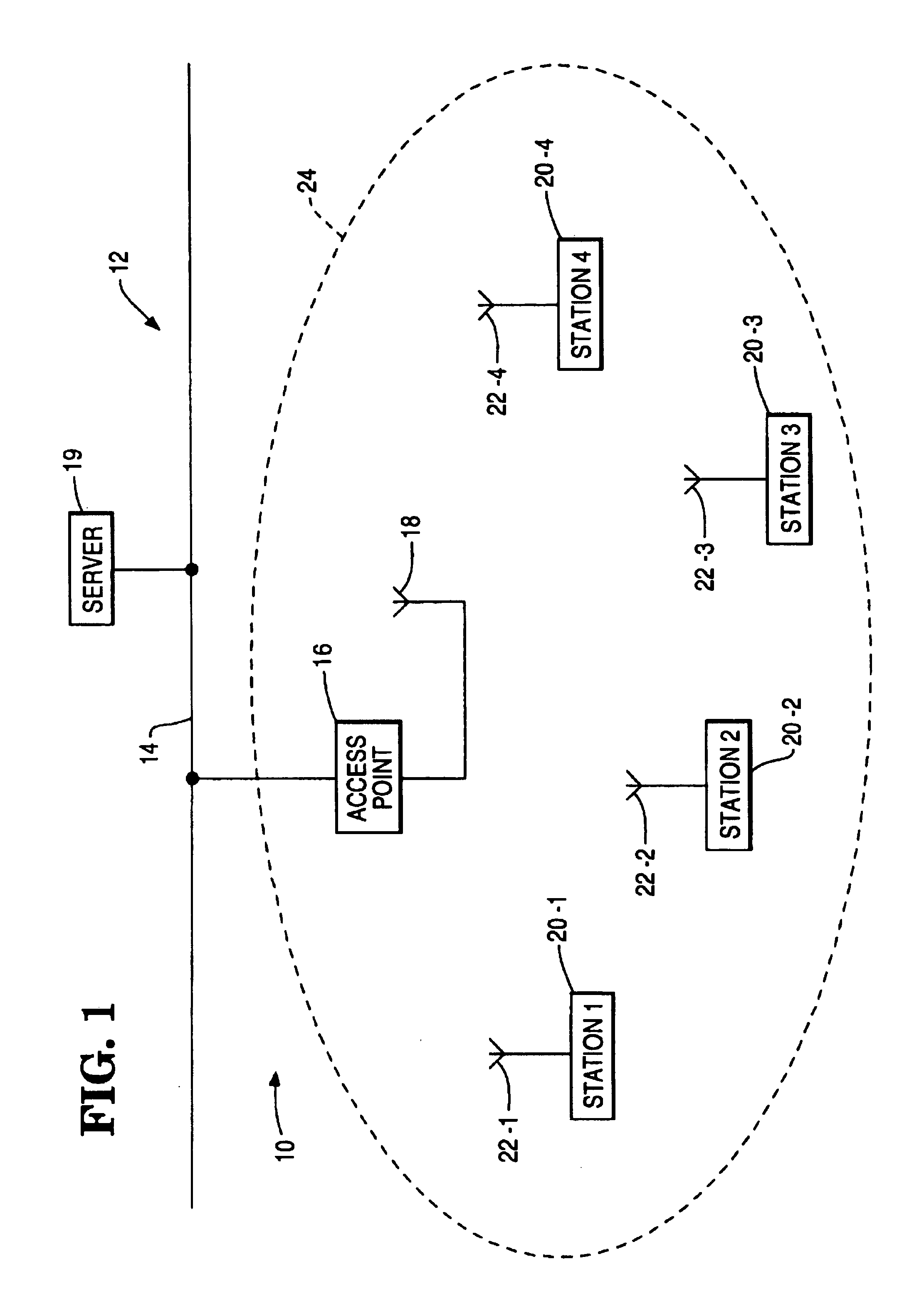
[0035]Although, in the above description, it has been assumed that the stations 20 are operating in power-save mode throughout, it will be appreciated that it is possible that a station 20 can dynamically select to be in power-save mode or continuous-active mode, the access point 16 being informed of all mode changes. When a station 20 is operating in continuous-active mode, the message buffering system is by-passed and messages are sent to the station directly when they arrive. Where data traffic to a station is predictable to a certain extent, an automatic procedure may be employed to keep the station in continuous-active mode prior to the expected traffic, and return it to power-save mode when no further traffic is expected. Thus, for example, each time a station 20 sends a message (via the access point 16) it could be controlled to remain in continuous-active mode for a predetermined time, sufficient to allow for a response message to be received in normal circumstances. The acc...

first embodiment

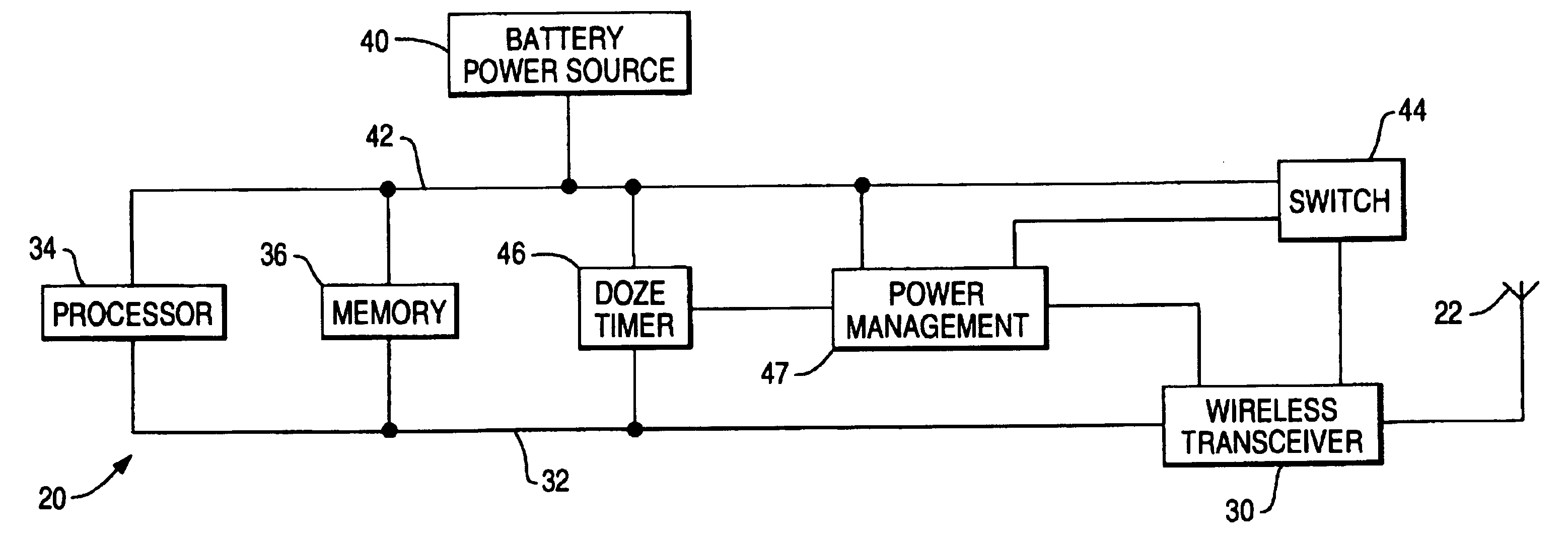
[0038]In a similar manner to that described for the first embodiment, the mobile wireless station 220 can operate either in a power-save mode, or in a continuous-active mode. In the power-save mode, the station 220 can be in an awake state, in which it is fully operational, or in a doze state, in which the wireless transceiver 230 operates at a reduced power level.

[0039]The network 210 operates in accordance with a power saving scheme, the principles underlying which will now be described. At initial start-up, one of the stations 220, assumed here to be the station 220-1, will assume the role of master station, and commences to transmit PSYNC messages (to be described) at regular intervals. The PSYNC messages are broadcast messages and therefore received by all stations. Preferably, each station 220 initially listens for a PSYNC message for a predetermined time, and if none is received, assumes the role of master station. The PSYNC messages include a portion identifying the message ...


PUM


Abstract

A wireless data communication system is operable in a power saving mode wherein stations are synchronized to be in an awake state to receive synchronizing messages (TIM, PSYNC) and traffic indicator information and are changed to a doze state if they are not to receive data messages. In one embodiment all stations (20) communicate via a base station access point (16), which broadcasts synchronizing messages (TIM) at regular intervals identifying stations (20) that are to receive data messages. In another embodiment all stations (220) communicate directly with one another, one station assumes the role of a master station and broadcasts synchronizing messages (PSYNC), and stations (220) desiring to transmit data messages transmit traffic indicator messages (PTIM) to the appropriate destination stations (220), in a synchronized awake period just before the next synchronizing message (PSYNC) is expected to arrive.

Description

BACKGROUND OF THE INVENTION[0001]This invention relates to wireless data communication systems.[0002]A recent development in the field of local area networks (LANs), has been the introduction of wireless communication in such networks. Another development has been the introduction of portable, battery-operated devices for use in such wireless networks.[0003]International Patent Application No. WO 92 / 19059 discloses a wireless data communication system which includes a cable-based network to which are attached controllers which maintain a portable device in communication with the network for data transfer. The portable unit transmits polling packets at regular intervals. Normally, a response packet is received from the current controller. If no response packet is received for a predetermined number of attempts, the portable unit initiates a procedure for registering with a new controller. The portable unit is powered by a battery which supplies power to the unit's transceiver and pac...

Claims


Application Information

Patent Timeline
IPC IPC(8): H04B7/14
CPCH04W52/0216Y02D30/70
Inventor VAN BOKHORST, HENDRIKCLAESSEN, ALBERTUS M. G.DIEPSTRATEN, WILHELMUS J. M.HAAGH, JOHANNES P. N.MOELARD, HENDRIKMONTEBAN, LEOMUD, RIENK
Owner AGERE SYST INC
Why Eureka
Try Eureka