
Practice ammunition

Inactive Publication Date: 2008-09-09
NICO PYROTECHNIK HANNS JUERGEN DIEDRICHS GMBH & CO KG
View PDF22 Cites 31 Cited by
  • Summary
  • Abstract
  • Description
  • Claims
  • Application Information

AI Technical Summary

Benefits of technology

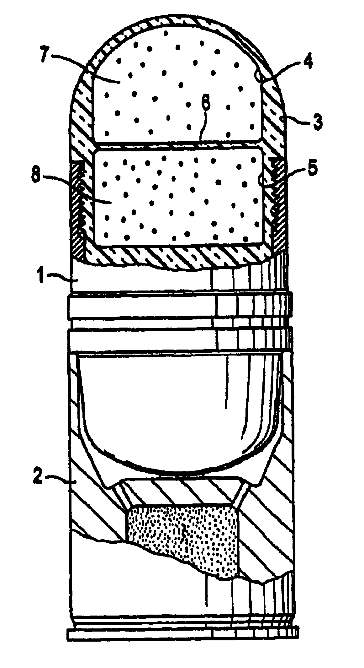
[0007]In accordance with the invention, the compartments containing the chemical components are broken up as early as in the initial and / or the twist acceleration phases. The compartments are individually contained in a hood made of an optically transparent material and located at the head of the practice projectile. On impact, the hood will burst and release the marking agent to identify the impact side. At the same time, the optically transparent hood enables the marking—such as the chemoluminescent effect of the chemically reacting components—to be perceived along the entire trajectory of the practice projectile. The chemical components are selected to produce a sustained luminous effect lasting for an extended period of time, enabling the practice projectile to be optically tracked along its entire trajectory, and additionally to mark the impact site.

Problems solved by technology

However, the colored powder is visible only under conditions of sufficient brightness; under low light or at night it will not be visible unless powerful night viewing equipment is used.

Method used


Image

  • Practice ammunition
  • Practice ammunition

Examples


Embodiment Construction

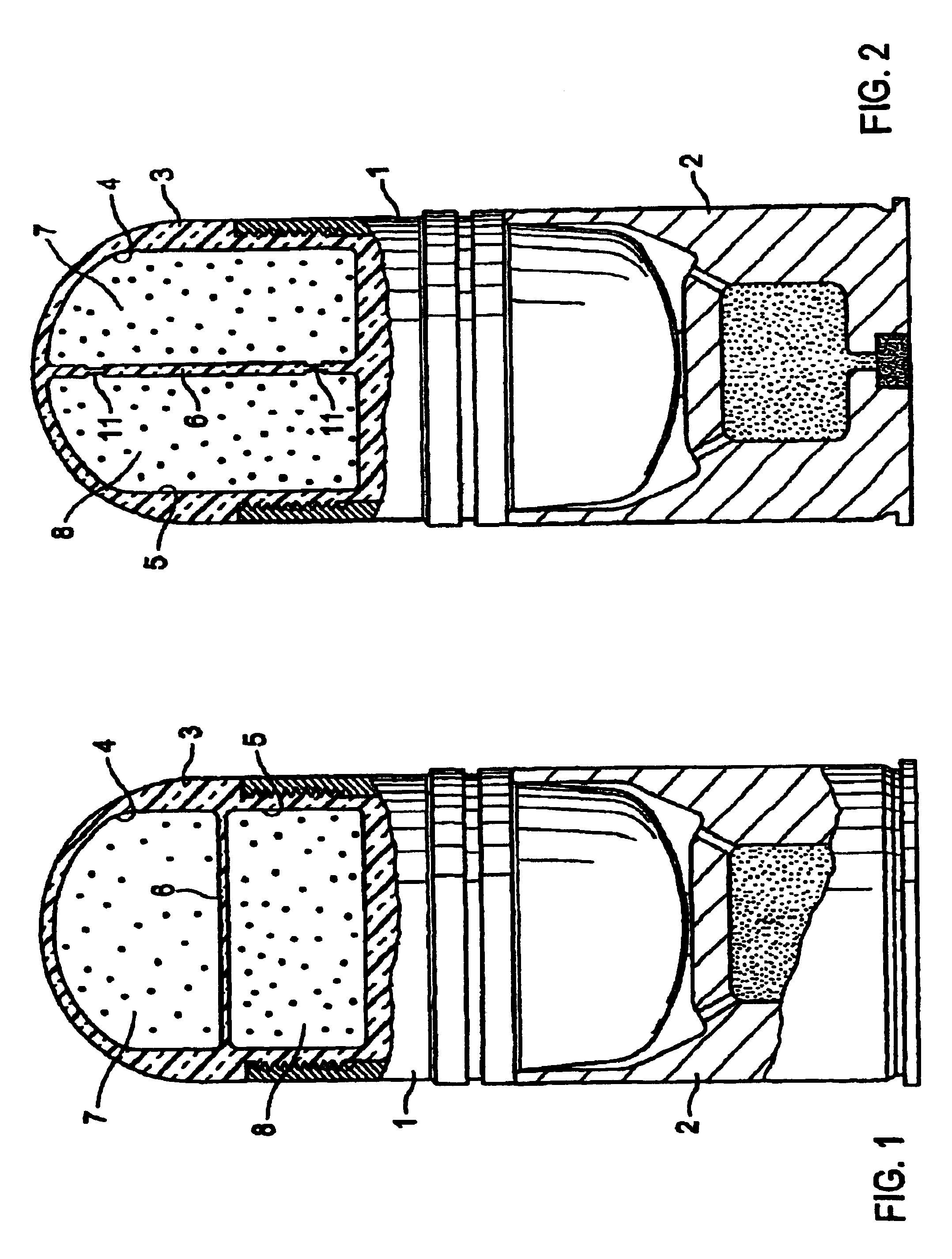
[0014]The preferred embodiments of the present invention will now be described with reference to FIGS. 1 and 2 of the drawings. Identical elements in the various figures are designated with the same reference numerals.

[0015]FIG. 1 shows a practice projectile 1 received in a cartridge case 2. The head of practice projectile 1 has a hood 3 consisting of a transparent material—such as a plastic material—and covering a first compartment 4 and a second compartment 5. The two compartments are arranged one on top of the other and are separated from each other by a partition 6 therebetween. The first compartment is filled with a first chemical component 7 such as an oxidant and the second compartment is filled with a second chemical component 8 such as a reducing agent.

[0016]When the partition is broken up by the force of the acceleration generated during firing, for example, the chemical reaction of the two chemical components causes chemoluminescent light to be emitted which is visible th...


PUM


Abstract

A practice ammunition projectile comprises a head which bursts when the projectile strikes a target and contains a marking agent which optically indicates the point of impact after the head has burst. The marking agent consists of several chemical components (7, 8) which are each contained in separately breakable compartments (4, 5) within a burstable hood at the head of the projectile. When the compartments (4, 5) break open the compartments combine and undergo a chemical reaction which creates an optical mark. The hood is formed of an optically transparent material to enable the trajectory of the projectile to be tracked.An ammunition cartridge comprising a hollow projectile and a cartridge case with a propellant charge, the projectile comprising a projectile head designed to withstand the forces applied when the projectile is fired from a gun and designed to burst when the projectile strikes a target. A marking agent is disposed in the head for optically marking the impact with the target after the head has burst. The marking agent includes a plurality of chemical components each received in a separate frangible compartment in the head. These components are mixed and react chemically with each other when the compartments break up, causing the mixed components to luminesce. The compartments are designed to be broken up by the initial acceleration and / or the centrifugal forces on the projectile when the projectile is fired from a gun, while retaining the chemical components in the head. The components are therefore mixed at the time the projectile is fired from a gun and luminesce by the time the projectile strikes the target.

Description

BACKGROUND OF THE INVENTION[0001]The invention relates to practice ammunition including a marking agent.[0002]In the use of practice ammunition of this kind—such as practice shells and practice bombs—it is important to mark the impact site so as to obtain optimum practice results. To this end, the practice ammunition comprises a head with a chamber containing a marking agent, preferably a powder with a reddish color. The head is made of a material which when striking a target will burst and release the colored powder. The powder is scattered within some radius about the impact site, thus marking the latter optically. However, the colored powder is visible only under conditions of sufficient brightness; under low light or at night it will not be visible unless powerful night viewing equipment is used.[0003]The U.S. Pat. No. 5,018,450 discloses a practice projectile in which the marking agent is contained in a burstable hood at the head of the practice projectile. The marking agent ha...

Claims


Application Information

Patent Timeline
IPC IPC(8): F42B8/00F42B12/38F42B12/40
CPCF42B8/12F42B12/38F42B12/40
Inventor HAESELICH, DETLEF TED
Owner NICO PYROTECHNIK HANNS JUERGEN DIEDRICHS GMBH & CO KG
Learn More