Ripple cancellation circuit for ultra-low-noise power supplies

a power supply and cancellation circuit technology, applied in the direction of power conversion systems, dc-dc conversion, instruments, etc., can solve the problems of unintended noise sensitivity, adversely affecting performance, and low power requirements

Inactive Publication Date: 2009-09-08
F POSZAT HU
View PDF18 Cites 13 Cited by
  • Summary
  • Abstract
  • Description
  • Claims
  • Application Information

AI Technical Summary

Problems solved by technology

Unfortunately, a concomitant of low power requirements is often sensitivity to unintended noise or fluctuations in the applied power.
It is less apparent but true that small-percentage variations or noise on the applied powering voltage may result in degradation of the operating characteristics of semiconductor and other devices and the circuits in which they operate, which may adversely affect the performance.
However, transformers operating at 60 Hz tend to be much larger than is desirable in modern miniaturized equipment.
However, batteries have the same general problem as that of mains powering, namely that available direct voltage does not necessarily correspond with the desired operating voltage.

Method used


Image

  • Ripple cancellation circuit for ultra-low-noise power supplies
  • Ripple cancellation circuit for ultra-low-noise power supplies
  • Ripple cancellation circuit for ultra-low-noise power supplies

Examples


Embodiment Construction

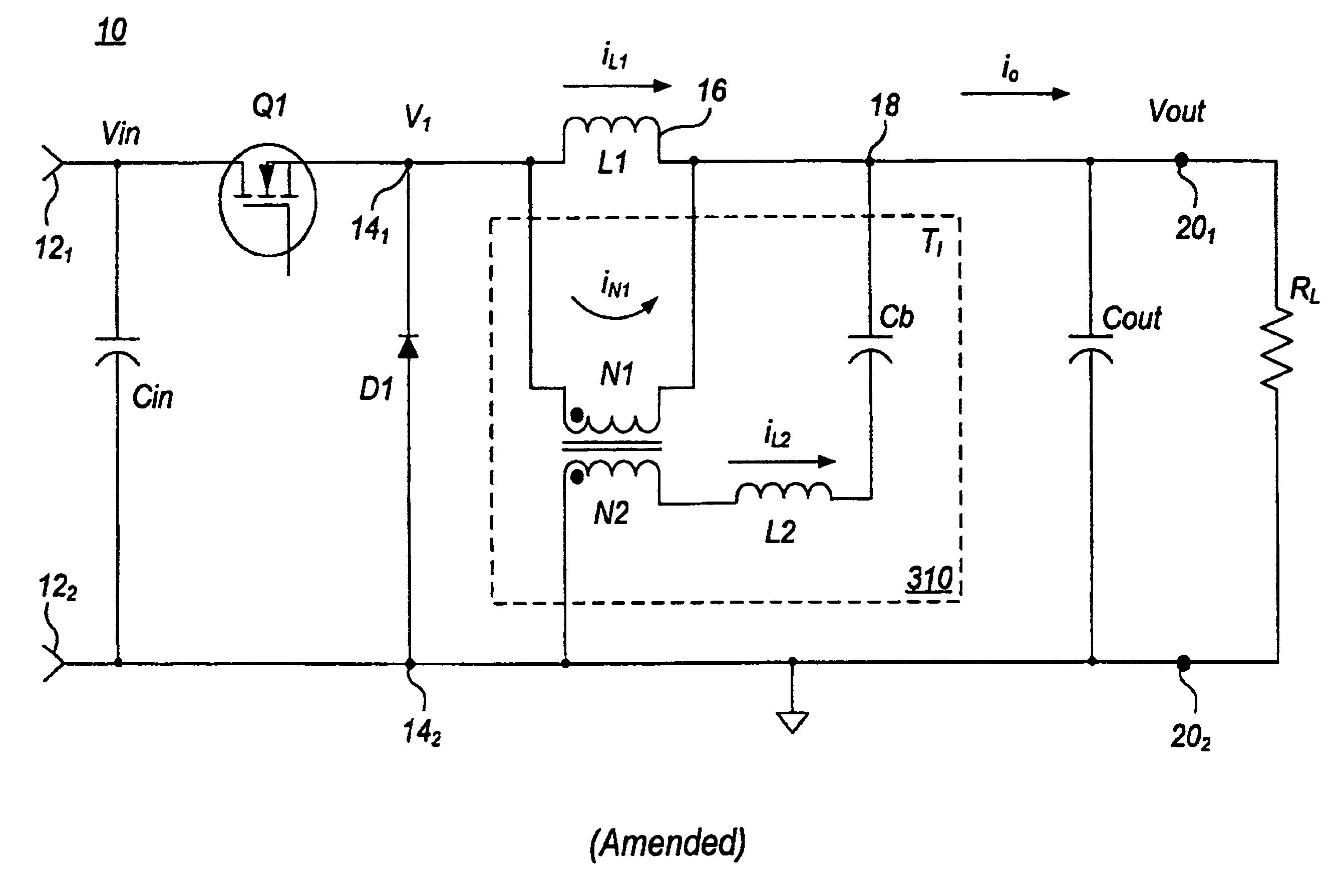
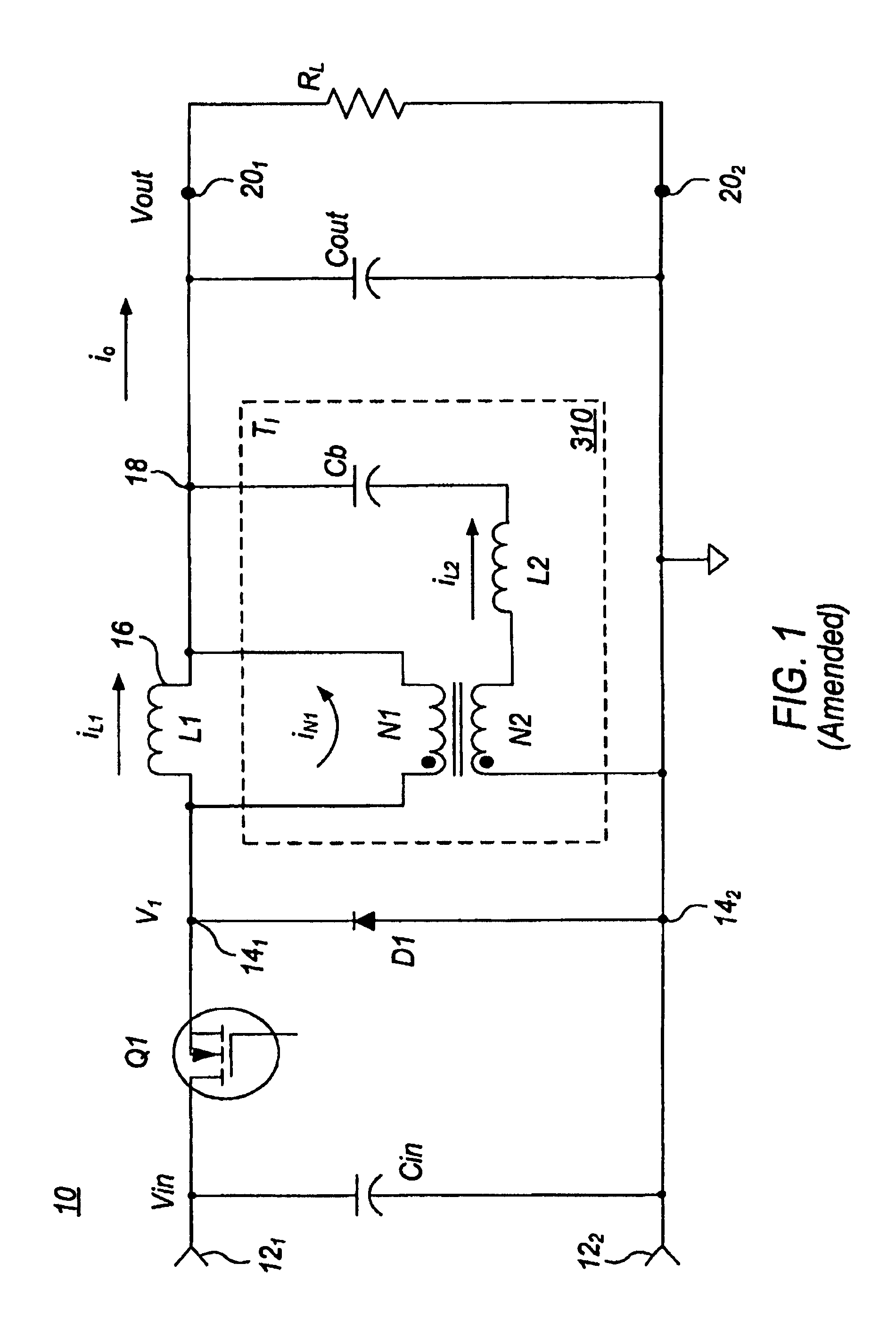
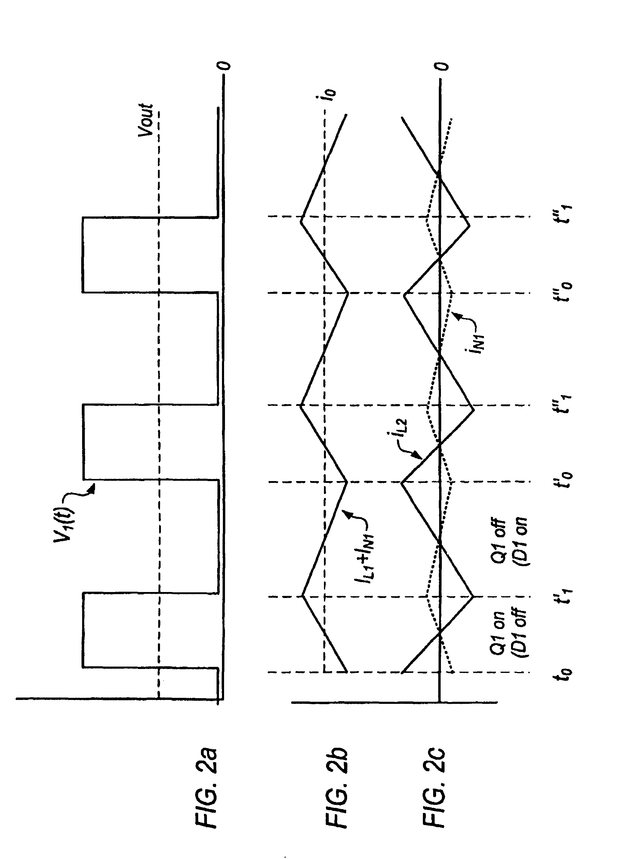
[0020]In FIG. 1, an unregulated or “raw” direct voltage Vin is applied from a source (not illustrated) to regulator or power supply 10 input terminals 121, and 122. A controllable switch illustrated as a field-effect transistor (FET) Q1 is controlled, by means which are not illustrated but which are well known in the art, to switch in a recurrent manner. The switching may be periodic or aperiodic, but the effect is to recurrently apply the Vin voltage “across” terminals 141, and 142, as illustrated by plot v1(t) of FIG. 2a in the intervals t0 to t1, t0′ to t1′, and t0″ to t1″. Those skilled in the art will understand that the words “across” and “between” as used in electrical contexts have no particular physical meaning as might be ascribed in a mechanical or common context.

[0021]As illustrated in FIG. 1, power supply 10 includes an inductor or inductive arrangement 16 connected in “series” with an output filter capacitor Cout, and the resulting series combination or combined circui...


PUM


Abstract

A low-ripple power supply includes a storage capacitor coupled across load terminals, and an inductor connected to a source of voltage including a varying or pulsatory component and a direct component, for causing a flow of current to said capacitor through the inductor. The varying component of the inductor current flowing in the capacitor results in ripple across the load. A winding is coupled to the inductor for generating a surrogate of the varying inductor current. The surrogate current is added to the inductor current to cancel or reduce the magnitude of the varying current component. This cancellation effectively reduces the varying current component flowing in the storage capacitor, which in turn reduces the ripple appearing across the load terminals.(121)

Description

FIELD OF THE INVENTION[0001]This invention relates to direct-voltage power supplies, and more particularly to low-noise or low-ripple power supplies.BACKGROUND OF THE INVENTION[0002]Much of the advance in standard of living over the past twenty or so years results from the use of advanced communications, data processing, and environmental sensing techniques. The devices used in such communications, processing, and sensing generally become more useful as their sizes are decreased, such that more of them can be used. For example, computers and cellular phones require ever-smaller elements, and become more capable as the number of devices which can be accommodated increases. Similarly, lightweight and reliable sensors can be used in large numbers in vehicles to aid in control and, in the case of spacecraft and military vehicles, to aid in carrying out their missions.[0003]Most modern semiconductor devices, and other devices important for the above purposes, are generally energized or b...

Claims


Application Information

Patent Timeline
Patent Type & Authority Patents(United States)
IPC IPC(8): H02M1/14G05F1/56H02J1/02H02M3/156H02M3/337
CPCH02J1/02H02M1/14H02M3/156H02M3/33573
Inventor STEIGERWALD, ROBERT LOUISSCHUTTEN, MICHAEL JOSEPH
Owner F POSZAT HU
Why Eureka
Try Eureka