Vertical wind tunnel training device

Inactive Publication Date: 2011-12-13
IFLY HLDG
View PDF32 Cites 11 Cited by
  • Summary
  • Abstract
  • Description
  • Claims
  • Application Information

AI Technical Summary

Benefits of technology

[0024]The primary aspect of the present invention is to provide a vertical wind tunnel amusement device having a flight chamber located on the inlet side of the fans for improved airflow control and stability.
[0034]In an alternate embodiment, return air ducts are connected between the outlet of the fans and the inlet of the wind tunnel. Each return air duct has an outlet damper and an inlet damper. A portion of the airflow is blown out of the outlet damper. An equivalent portion of air is drawn into the inlet damper and then into the wind tunnel. This arrangement allows heated airflow air to be replaced with cooler ambient air, thereby allowing a user to adjust the temperature in the flight chamber for flyer comfort.

Problems solved by technology

As a result, access to the wind tunnels is limited at best.
These wind tunnels are not generally designed nor intended to be used by persons for the purpose of enjoyment or for learning to skydive.
Consequently, none of these wind tunnels are used for general amusement purposes.
None of these wind tunnels are available for use by essentially untrained people or by those with limited instruction.
None of these wind tunnels are available to the public for use as an amusement ride.
Further, the design of these prior art wind tunnels are not “user-friendly” for the purposes of use and enjoyment by users such as those who frequent amusement parks and the rides they offer.
The prior art wind tunnels do not offer any means of enhancing the ride experience such as with a concurrent / interactive video presentation, nor do they offer a means of airflow control adopted to meet the needs of an operator providing thrill rides to the public.

Method used


Image

  • Vertical wind tunnel training device
  • Vertical wind tunnel training device
  • Vertical wind tunnel training device

Examples


Embodiment Construction

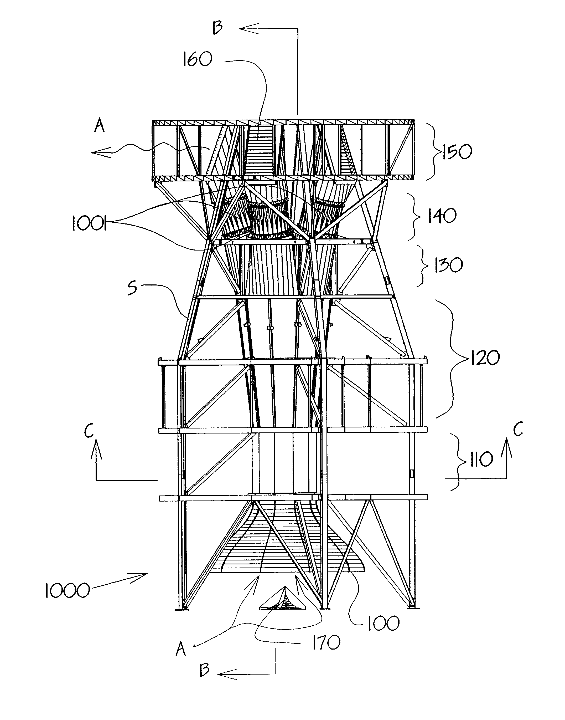
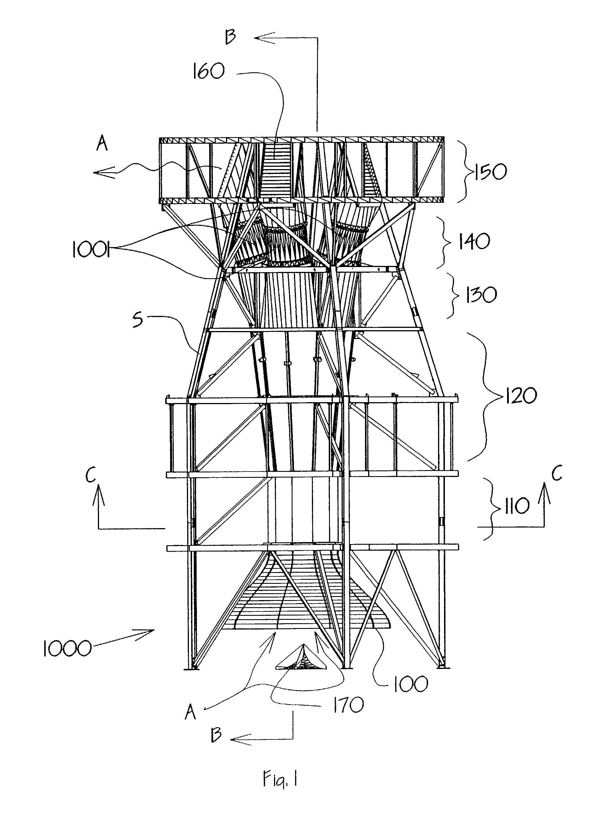
[0057]Reference is made to FIG. 1, a front elevation view of the preferred embodiment. The preferred embodiment comprises a vertical wind tunnel 1000 having a number of component parts. Inlet contraction 100 is connected to the lower end of the flight chamber 110. Diffuser 120 is immediately connected above the flight chamber 110. Connected above the diffuser 120 is transition 130 from diffuser 120 to the fans 140. Connected above fans 140 is the radial diffuser assembly 150. In operation, inlet contraction 100 allows the airflow A to be directed into the flight chamber 110 in a controlled manner. Anti-vortex device 170 prevents the formation of undesirable vortices or “tornadoes” in the inlet to the flight chamber. The means of design of the inlet contraction and its effects on the inlet airflow is well known in the art. The shape of the inlet contraction allows a relatively smooth airflow to enter the flight chamber. This reduces the amount of turbulence in the flight chamber, the...


PUM


Abstract

The present invention is a vertical wind tunnel amusement device. The device comprises a flight chamber wherein a user may experience a freefall through the atmosphere from the safety of an enclosed flight chamber. Airflow sufficient to fully support a user within the flight chamber is induced by a plurality of fans connected above the flight chamber through a duct. A staging area having openings to the flight chamber is adjacent to the flight chamber. A user may enter or retreat from the flight chamber at will through the staging area openings without significantly adjusting the airflow velocity in the flight chamber. A control room is adjacent to the fight chamber whereby an operator may observe a user or users within the flight chamber and thereby safely control the operation of the fans. A projection room is also adjacent to the flight chamber whereby a video of a skydiving experience may be displayed to a user within the flight chamber. A telemetry backpack may be worn by a user or users in the flight chamber so the user can interact with or choose the scenes being projected on the flight chamber.In alternate embodiment, return air ducts are used to return air from each fan to the wind tunnel inlet. Dampers are included on each return air duct thereby allowing the temperature of the airflow in the wind tunnel to be adjusted for user comfort.

Description

REFERENCE TO RELATED APPLICATIONS[0001]This application is a CIP of U.S. patent application Ser. No. 09 / 159,369 filed Sep. 23, 1998 now abandoned.FIELD OF THE INVENTION[0002]The present invention relates to the field of vertical wind tunnels, more particularly, to non-return flow vertical wind tunnels used as amusement devices.BACKGROUND OF THE INVENTION[0003]Wind tunnels are well known in the art. Wind tunnels are available in many types and styles depending upon the needs of the user. These include subsonic wind tunnels with and without return flow, transonic wind tunnels with and without return flow, vertical subsonic wind tunnels with and without return flow, supersonic and hypersonic wind tunnels with and without return flow, and compressible flow wind tunnels.[0004]The majority of the wind tunnels are used for research and testing purposes. These include testing of conventional aircraft, helicopters, parachutes and other aerodynamic devices, wing surfaces, control surfaces, su...

Claims


Application Information

Patent Timeline
IPC IPC(8): A63G31/00G09B9/08B64D23/00
CPCA63G31/00A63G2031/002A63G2031/005B64D23/00
Inventor KITCHEN, WILLIAM J.PALMER, MICHAEL
Owner IFLY HLDG
Why Eureka
Try Eureka