
Method and device for disinfecting and purifying liquids and gasses

a technology of liquid and gas, which is applied in the direction of electrodialysis, energy-based chemical/physical/physico-chemical processes, catalyst activation/preparation, etc., can solve the problems that the above-mentioned concentrators have never been used as hydrodynamic flow concentrators, and achieve high energy density zones, facilitate continuous interaction of diversity of energies, and facilitate high energy density zones

Inactive Publication Date: 2012-05-01
ATLANTIUM TECHNOLOGIES LTD
View PDF47 Cites 11 Cited by
  • Summary
  • Abstract
  • Description
  • Claims
  • Application Information

AI Technical Summary

Benefits of technology

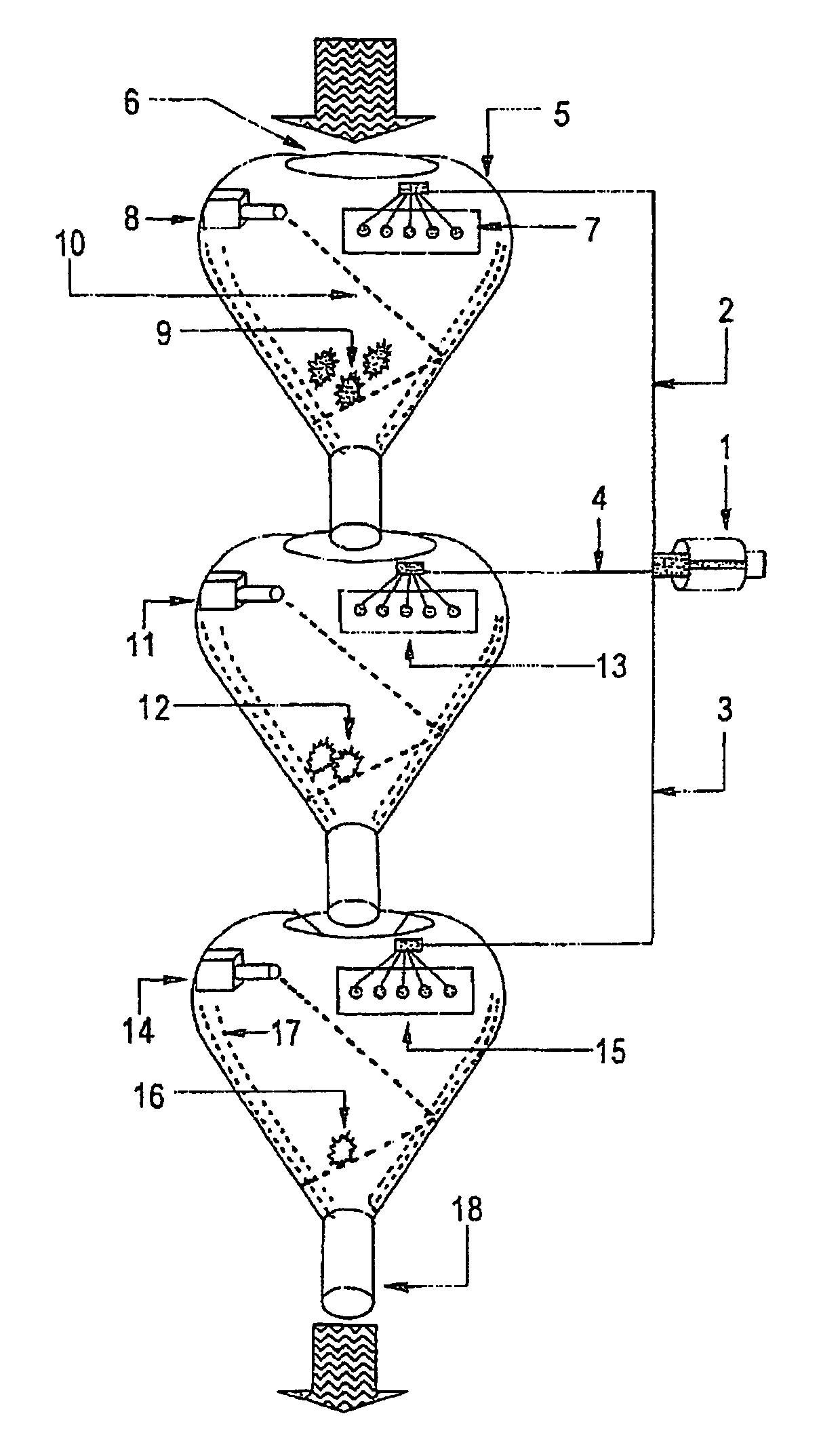
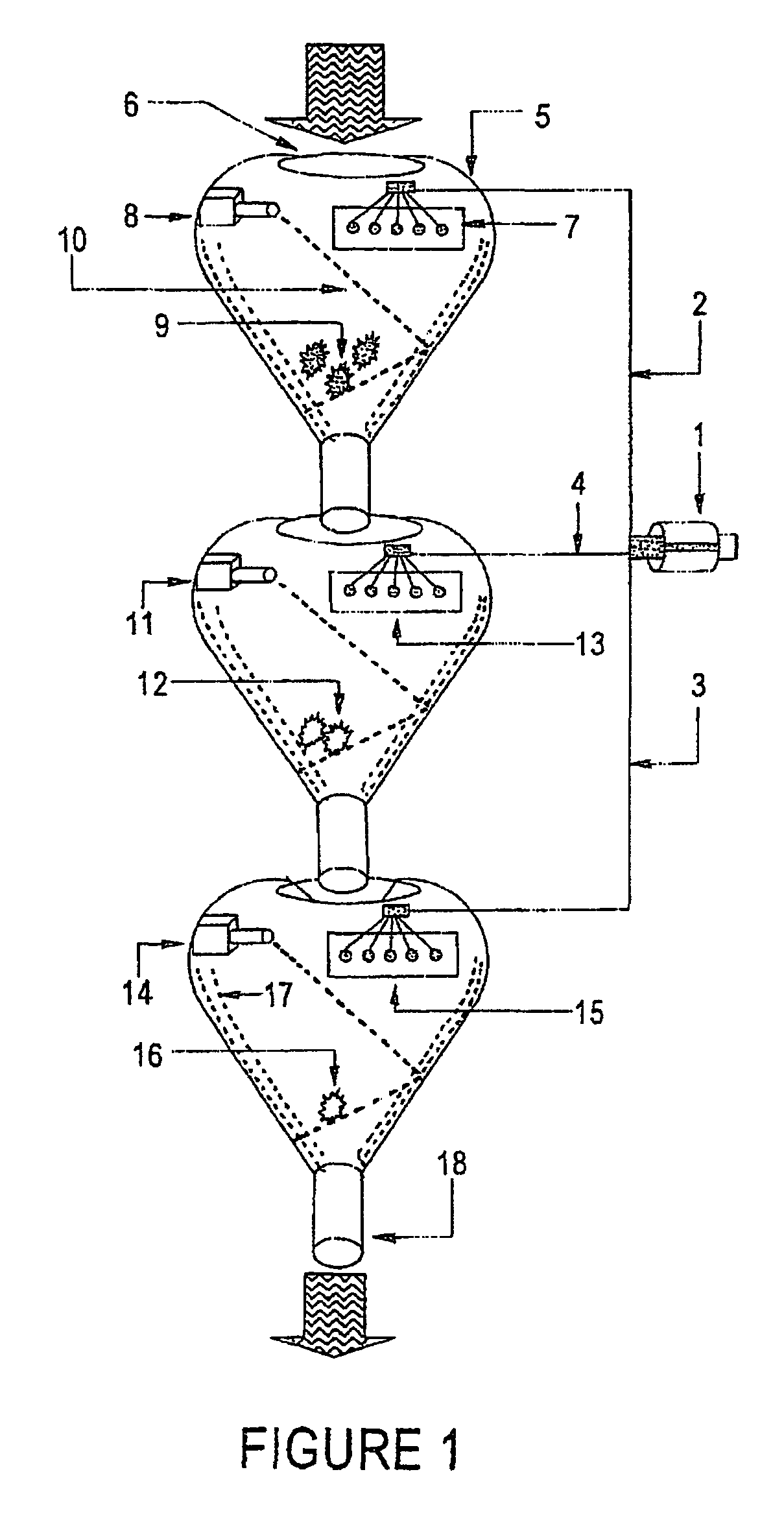
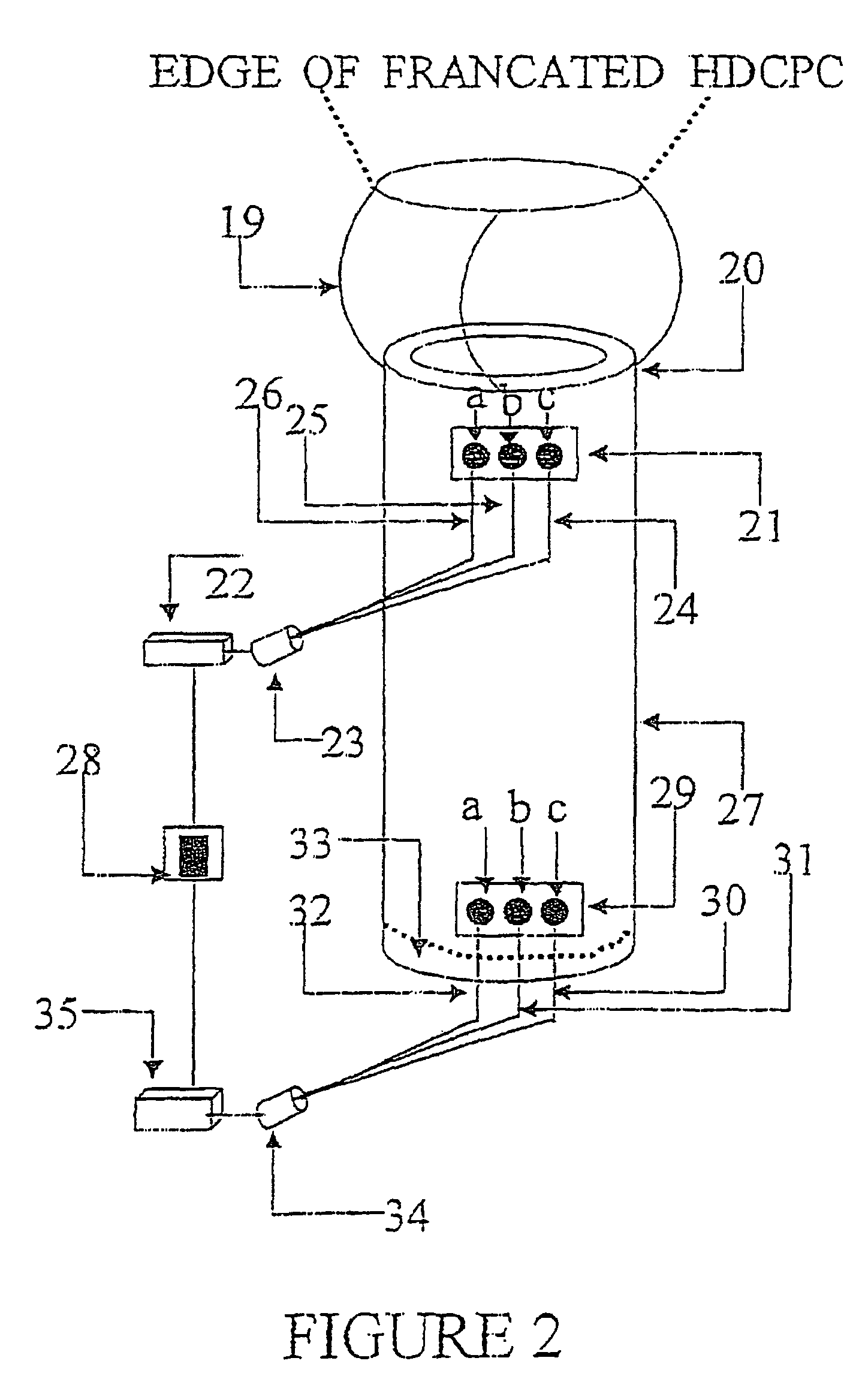
[0010]Surprisingly, it was found in the present invention, that using a compound concentrator as a concentrator or reactor in which both electromagnetic and acoustic energies interact while passing at the same time liquids and gasses through the reactor (having a single concentrator, and / or multi stage concentrator arrays) shaped reactor, enables disinfecting, and / or deodorizing and / or purification of the gasses and liquids with very high throughput efficiencies.
[0042]The present invention provides a novel methodology wherein a plurality of energies interact in space and time to produce a high energy density zone, which is especially beneficial for disinfecting, dissolving and neutralizing pollutants in liquids and gasses (such as water & air). Furthermore, the method of the present invention facilitates continuous interaction of diversity of energies to form a high energy density zone.

Problems solved by technology

Furthermore, the above mentioned concentrators have never been used as hydrodynamic flow concentrators.

Method used


Image

  • Method and device for disinfecting and purifying liquids and gasses
  • Method and device for disinfecting and purifying liquids and gasses
  • Method and device for disinfecting and purifying liquids and gasses

Examples


Embodiment Construction

[0056]The present invention provides a novel and unobvious method for (a) harnessing diversity of energies into a modular compounded concentrator geometry, (b) compounding and (c) catalytically and / or interactively impacting (d) a predetermined amount of diversified energies produced simultaneously within the geometry through which liquids or gasses containing pollutants or noxious species flow, so that the pollutants become more innocuous as a result of (e) time resolved synchronized impact diversity of wavefronts for the purpose of forming a maximized energy density of all wavefronts in a (predetermined) space or zone which zone is useful for disinfecting, dissolving and / or neutralizing or inactivating the pollutants in the liquids or gasses over a predetermined period of time. Furthermore, the Failure Modes Evaluation and Criticality Assessment (FME / CA) surpass. Limitations imposed by conventional systems using TiO2 optical catalyst where catalyst triggering relies heavily on the...


PUM

PropertyMeasurementUnit
Thicknessaaaaaaaaaa
Thicknessaaaaaaaaaa
Thicknessaaaaaaaaaa

Abstract

The present invention relates to a method for disinfecting and purifying liquids and gasses comprising; a) passing said liquids or gasses through a reactor or a combination of reactors, having a truncated compounded concentrator geometry; and b) simultaneously delivering and concentrating diversified electromagnetic and acoustic energies into a specific predetermined inner space of said compounded concentrator reactor, forming a high energy density zone in said reactor or reactors over a predetermined period of time. The reactor according to the present invention is preferably a compounded parabolic concentrator or a compounded ellipsoidal concentrator. The electromagnetic energy delivered and concentrated into and inside the reactor can be of any range of the electromagnetic spectrum, such as ultra-violet, visible, infra-red, microwave etc., or combination thereof. The acoustic energy is of any suitable frequency. The radiation source delivering the electromagnetic radiation can be enclosed within the reactor or can be external to the reactor.

Description

FIELD OF THE INVENTION[0001]The present invention relates to a method for simultaneously disinfecting and purifying liquids and gasses. More specifically, the present invention relates to a method for disinfecting and purifying liquids and gasses by passing the liquids and / or gasses through a reactor of a compounded concentrator geometry, in particular, a compounded parabolic concentrator geometry, and simultaneously concentrating a plurality of launched and / or delivered, and / or diversified energies in motion into a specific predetermined inner space of the reactor to form a high energy density zone. The energies include acoustic and / or ultrasonic transient cavitation and electromagnetic energy from a variety of ranges of the electromagnetic spectrum (e.g., ultra-violet, visible, infra-red, microwave etc.).[0002]The inner surface of the reactor is preferably covered by a thin layer of photo-catalyst such as titanium oxide and the inner surface is optionally grooved, or sub-wavelengt...

Claims


Application Information

Patent Timeline
IPC IPC(8): C02F1/30C02F1/48A61L2/02A61L2/08A61L2/10A61L2/12A61L2/232A61L9/00A61L9/18A61L9/20B01D53/86B01D61/08B01J19/10B01J19/12B01J21/06B01J35/02B01J37/02C02F1/32C02F1/34C02F1/44C02F1/72C02F9/00
CPCA61L2/08A61L2/232C02F1/30C02F1/302C02F1/32C02F1/441C02F1/725C02F9/00C02F2201/3227Y02W10/37C02F1/72
Inventor TRIBELSKY, ZAMIRENDE, MICHAEL
Owner ATLANTIUM TECHNOLOGIES LTD
Learn More