Aerial photography mount

a technology for mounting mounts and photography, applied in the field of aerial photography mounts, can solve problems such as degrading the visual quality of images, and achieve the effects of reducing the amount of vibration, improving the degree of vibration reduction, and low friction

Inactive Publication Date: 2014-07-01
WAWRO CHRISTOPHER
View PDF20 Cites 3 Cited by
  • Summary
  • Abstract
  • Description
  • Claims
  • Application Information

AI Technical Summary

Benefits of technology

[0005]The innermost member of the gimbal unit is a vertical gimbal post assembly that rotates around the yaw-axis within precision bearings that enable the upper and lower members to rotate freely about a middle member. The upper member can be connected to an imaging device such a still or video camera, or preferably, to a tripod head to which a camera is mounted. The bottom member has a plate for mounting gyroscopic stabilizers. The forces generated by the gyroscopic stabilizers keep the gimbal assembly steady in space thus allowing for smooth image capture with fluid, near-friction free movement for panning and counteracting movements induced by yaw, roll, and pitch. The upper and lower members are connected, preferably by a bolt that runs through the middle member, and thus the upper and lower members rotate in unison.
[0012]Another advantage is that the framework is configured in a manner as to provide full adjustability of the unit. The gimbal suspension blocks can be adjusted independently for height. They can be set evenly or at any height to adjust for the attitude of the aircraft. This permits the gimbal unit to be leveled taking into account the default pitch of the aircraft in flight so that the camera is initially level with the horizon. The framework can be easily adjusted fore-and-aft and side-to-side by loosening fasteners on the cross rail and base rails and simply sliding them to the desired positions and tightening to lock them in place. This degree of adjustability allows for a high degree of control over placement of the camera within the confines of an aircraft.

Problems solved by technology

The taking of photographs and video from platforms such as aircraft and other modes of transportation is highly desirable for many applications but is made difficult because of the vibration that is transmitted to the camera causes movements that degrade the visual quality of the images.

Method used


Image

  • Aerial photography mount
  • Aerial photography mount
  • Aerial photography mount

Examples


Embodiment Construction

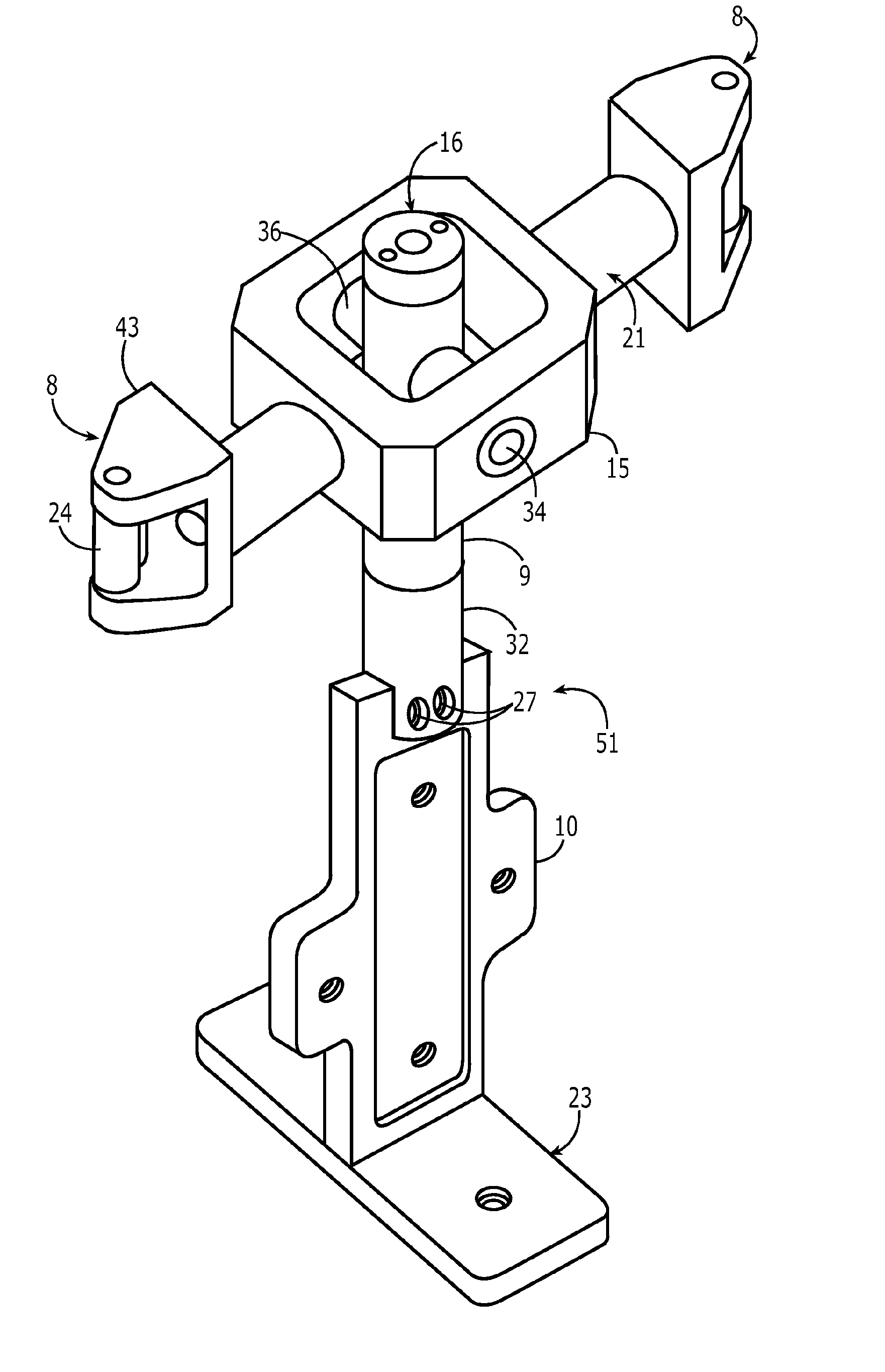
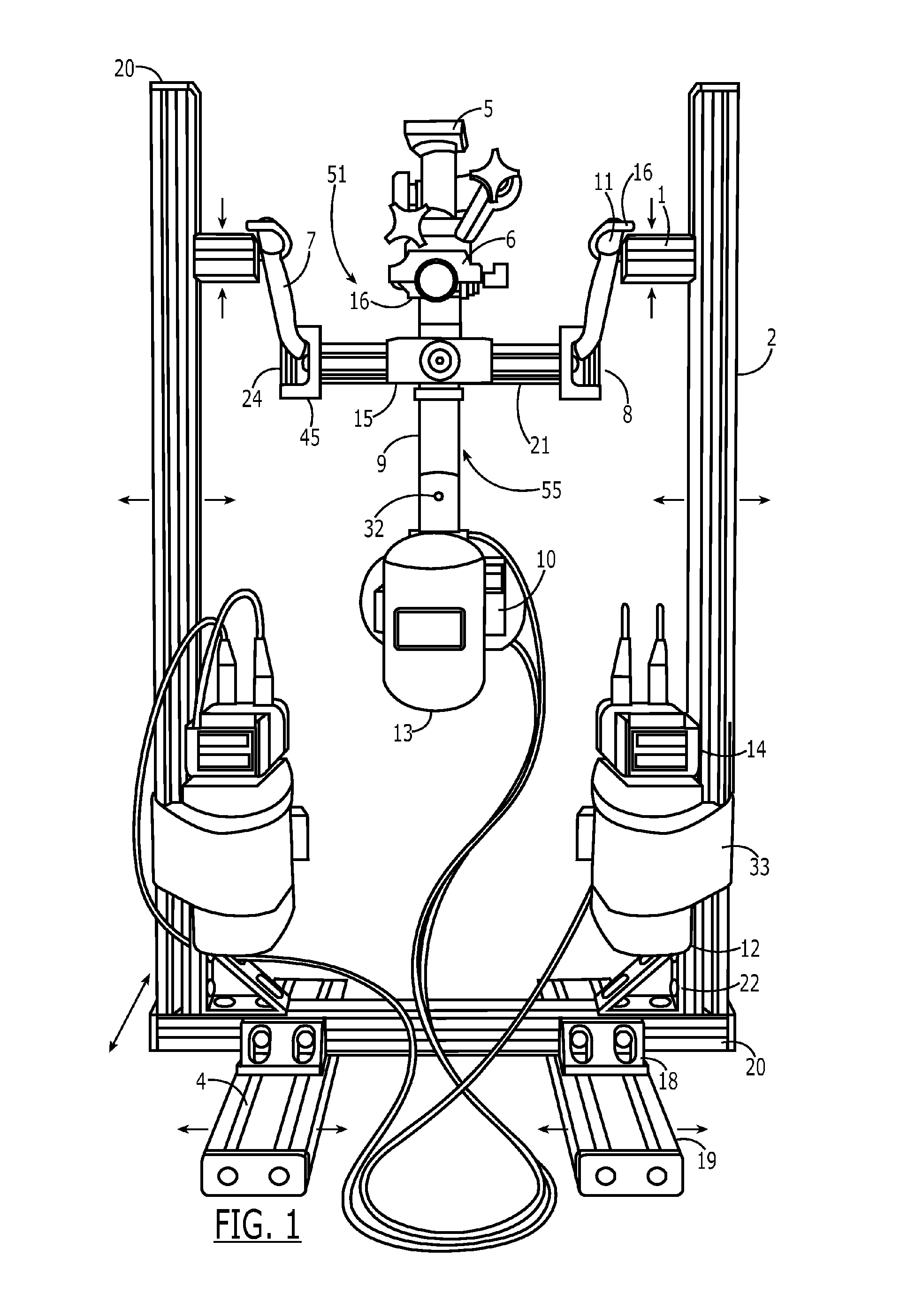
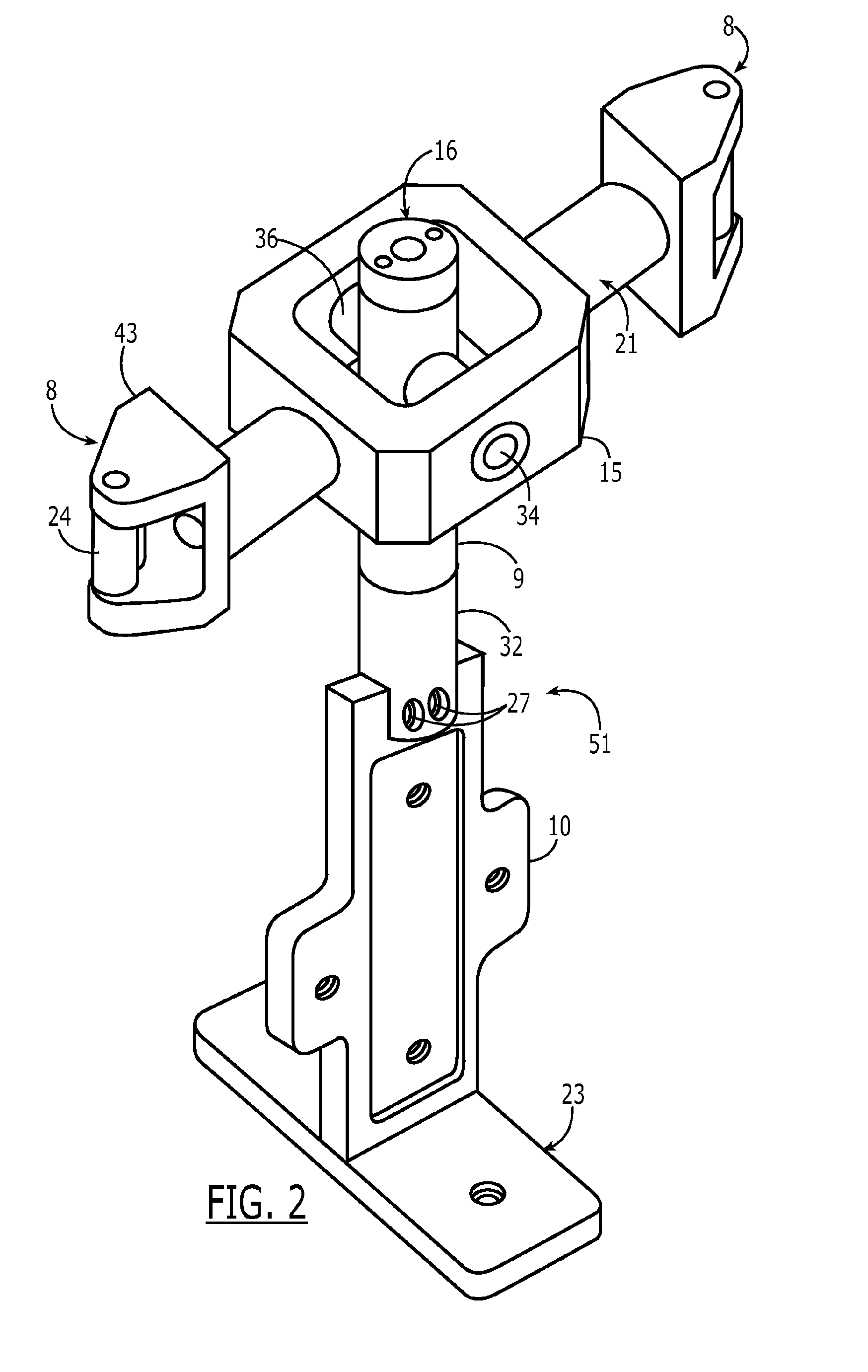
[0019]As shown in FIGS. 1-5, the preferred embodiment of the mount comprises a gimbal unit assembly 51 having a vertical post assembly 55, a central gimbal frame 15, and gimbal end suspension assemblies 8. The vertical gimbal post assembly 55 and the end suspension assemblies 8 are connected to the central gimbal frame 15 in a manner described more specifically below that permits a camera mounted to the vertical post assembly 55 to be moved freely and simultaneously through the yaw, roll, and pitch axes. The gimbal unit assembly 51 is suspended from elastic straps 7 that connect the end suspension assemblies 8 to hooks 11 on post blocks 1 which in turn are connected to a pair of posts 2. This means of suspension dampens the vibrations of the aircraft that would otherwise be transmitted to the gimbal unit assembly 51.

[0020]As shown in FIGS. 1 and 3, the vertical gimbal post assembly 55 comprises a camera mount base 16 for the attachment of a base mount plate 6 and tripod head 5 at th...


PUM


Abstract

An aerial photography mount that features a three-axis gimbal unit that is supported between two posts by elastic straps. Each of the axes rotates within precision bearings that enable smooth operation of a camera secured to the mount. The elastic straps, in conjunction with independently rotating bearings at the end suspension assemblies, provide a enhanced vibration isolation effect. The mount can be further stabilized by the attachment of gyroscopic stabilizers.

Description

CROSS-REFERENCED TO RELATED APPLICATIONS[0001]This application is a reissue application U.S. Pat. No. 8,434,950, the entirety of which is incorporated by reference, which claims the benefit of provisional application 61 / 448,959 which was filed on Mar. 3, 2011.FIELD OF THE INVENTION[0002]The invention relates generally to the field of aerial photography mounts.BACKGROUND OF THE INVENTION[0003]The taking of photographs and video from platforms such as aircraft and other modes of transportation is highly desirable for many applications but is made difficult because of the vibration that is transmitted to the camera causes movements that degrade the visual quality of the images. Compounding the problem is the need by many photographers to be able to selectively aim the imaging device within the confines of a small space. It is especially desirable that an aerial photography mount be portable and capable of being secured to a variety of aircraft, ground vehicles, and watercraft in a mann...

Claims


Application Information

Patent Timeline
Patent Type & Authority Patents(United States)
IPC IPC(8): G03B17/00G03B39/00G03B17/56
CPCF16M11/2092G03B2205/0007G03B17/561F16M11/123G03B17/00F16M13/022G03B15/006F16M11/00F16F7/00F16M2200/041F16F15/04G03B17/56F16M11/24
Inventor WAWRO, CHRISTOPHER
Owner WAWRO CHRISTOPHER
Why Eureka
Try Eureka