Anamorphic illumination of micro-electromechanical display devices employed in multimedia projectors

Inactive Publication Date: 2015-05-05
SEIKO EPSON CORP
View PDF30 Cites 1 Cited by
  • Summary
  • Abstract
  • Description
  • Claims
  • Application Information

AI Technical Summary

Benefits of technology

The present invention provides an apparatus and method to improve the brightness and uniformity of an MDD used in a multimedia projector. This is achieved by employing an anamorphic illumination system that illuminates the MDD with a tilted f / # perpendicular to the MDD hinge axis and a faster f / # parallel to the MDD hinge axis. This causes the incident and reflected light bundles to have elliptical, rather than circular cross-sections, resulting in more total light illuminating and reflecting off the MDD. A projection lens having an enlarged entrance pupil gathers and projects the reflected light bundle to produce a brighter projected image. Additionally, a second embodiment of the anamorphic illumination system utilizing micromirrors is also presented.

Problems solved by technology

This causes the incident and reflected light bundles to have elliptical, rather than circular cross-sections, resulting in more total light illuminating and reflecting off the MDD.

Method used


Image

  • Anamorphic illumination of micro-electromechanical display devices employed in multimedia projectors
  • Anamorphic illumination of micro-electromechanical display devices employed in multimedia projectors
  • Anamorphic illumination of micro-electromechanical display devices employed in multimedia projectors

Examples


first embodiment

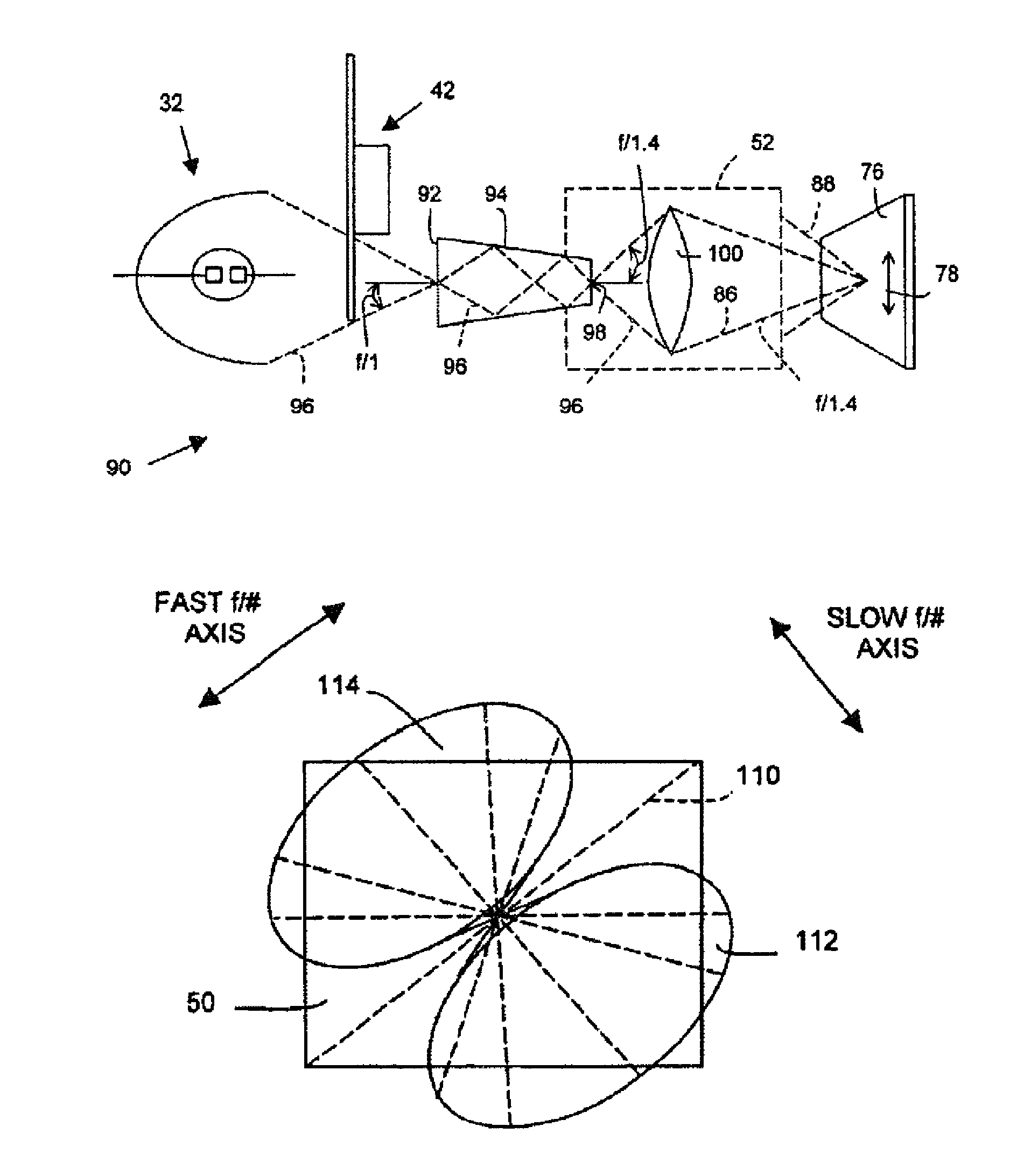
[0026]FIGS. 4A and 4B show respective top and side views of this invention that is suitable for use in a multimedia projector 90, which is architecturally similar to prior art multimedia projector 30 of FIG. 1. However, projector 90 does not include fold mirror 46, and MDD 50 is replaced by display device 76, which has an array of micromirrors that each pivot parallel to hinge axis 78 to control pixels in on- and off-states. Hinge axis 78 is parallel to an edge margin of display device 76. Display controller 56 (FIG. 1) controls the states of the array of micromirrors (pixels) to selectively reflect a projected image through projection lens 52.

[0027]Multimedia projector 90 preferably includes conventional light source 32 for propagating intense illumination through a color modulator, such as color wheel 42. Light exiting the color modulator enters an input aperture 92 of an anamorphic integrator tunnel 94. Light rays 96 propagate by multiple reflection through anamorphic integrator ...


PUM


Abstract

Micro-electromechanical display device (“MDD”)-based multimedia projectors (90, 120) of this invention employ an arc lamp (32), a color modulator (42), and anamorphic illumination systems (94, 121) for optimally illuminating a MDD (50, 76) to improve projected image brightness. MDDs employ off-axis illumination wherein incident and reflected light bundles are angularly separated about a hinge axis (78, 110) and the MDD is illuminated by the anamorphic illumination systems of this invention having a slow f / # parallel to the hinge axis and a faster f / # perpendicular to the hinge axis. The resulting anamorphic light bundles (86, 88, 112, 114) illuminate and reflect more light into and off the MDD and through a fast f / # projection lens.

Description

RELATED APPLICATION(S)[0001]Not ApplicableFEDERALLY SPONSORED RESEARCH OR DEVELOPMENT[0002]Not ApplicableTECHNICAL FIELD[0003]This invention relates to video and multimedia projectors and more particularly to improving the projected brightness of such projectors by employing anamorphic illumination of micro-electromechanical display devices employed therein.BACKGROUND OF THE INVENTION[0004]Projection systems have been used for many years to project motion pictures and still photographs onto screens for viewing. More recently, presentations using multimedia projection systems have become popular for conducting sales demonstrations, business meetings, and classroom instruction. Such multimedia projection systems typically receive from a personal computer (“PC”) analog video signals representing still, partial-, or full-motion display images that are converted into digital video signals for controlling a digitally driven image-forming device, such as a micro-electromechanical display d...

Claims


Application Information

Patent Timeline
IPC IPC(8): G03B21/00G03B21/14G03B21/26G03B21/28G02B5/32G02B27/09H04N5/74H04N9/31
CPCG03B33/08H04N5/7458H04N9/3114G03B21/2026G03B21/208G02B27/09H04N9/3152
Inventor PETERSON, MARK
Owner SEIKO EPSON CORP
Why Eureka
Try Eureka