Oval dilator and retractor set and method

A dilator, non-circular technology, used in bone drill guidance, medical science, surgery, etc., can solve problems such as tissue trauma

Inactive Publication Date: 2007-10-31
WARSAW ORTHOPEDIC INC
View PDF4 Cites 2 Cited by
  • Summary
  • Abstract
  • Description
  • Claims
  • Application Information

AI Technical Summary

Problems solved by technology

However, to provide such passage through a typical circular retractor using the dilation techniques described above would require a large diameter during placement of the dilator and tubular retractor to cause considerable trauma to the intervening tissue

Method used


Image

  • Oval dilator and retractor set and method
  • Oval dilator and retractor set and method
  • Oval dilator and retractor set and method

Examples


Embodiment Construction

[0019] In order to facilitate an understanding of the principles of the invention, the invention will now be described using specific language with reference to the embodiments shown in the drawings. It should be understood, however, that no limitation of the scope of the invention is thereby intended and that such changes and further modifications in the illustrated apparatus, as well as those described herein, would normally occur to one skilled in the art to which the invention pertains. Such a further application of the principles of the present invention is shown.

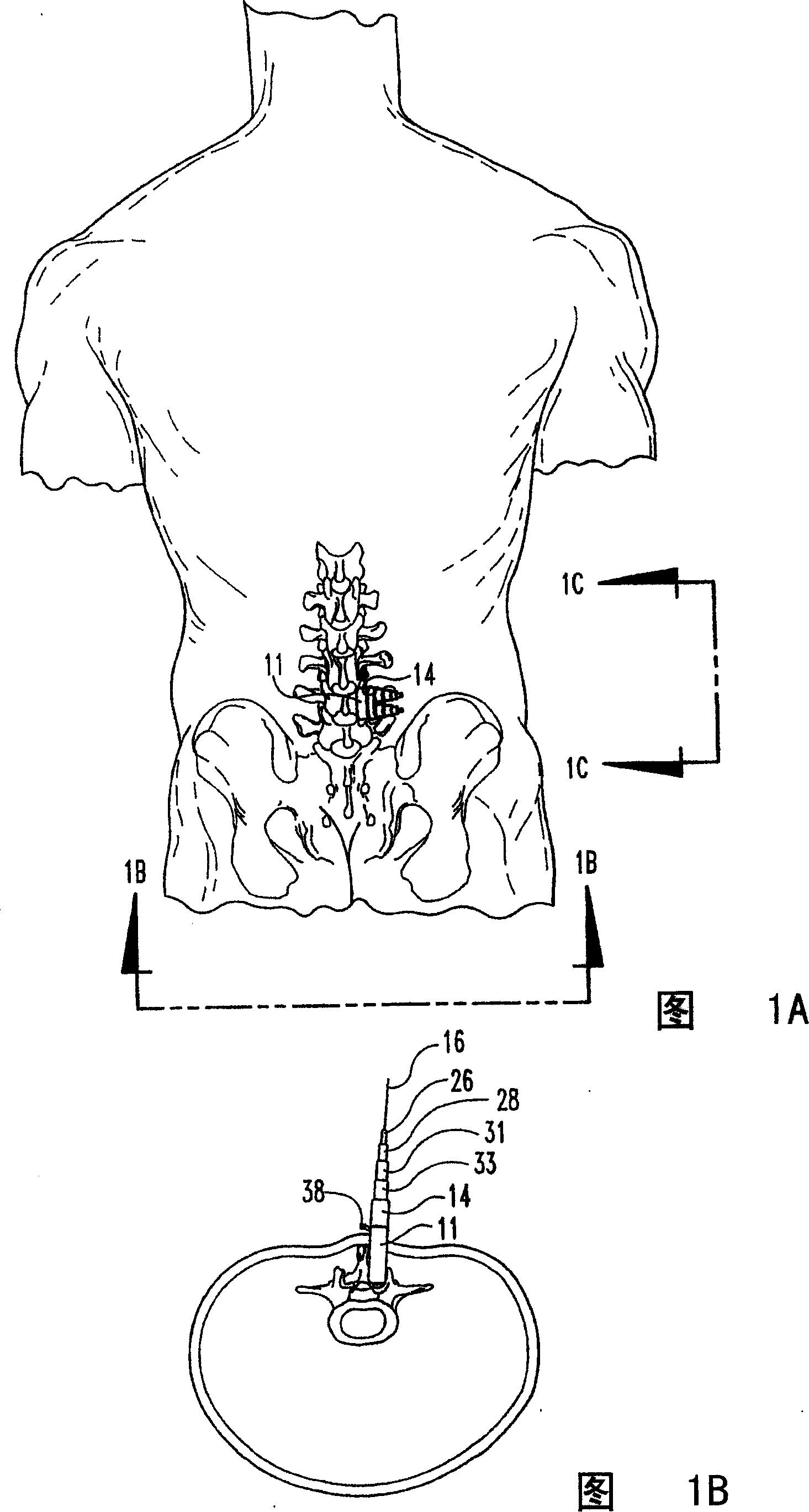
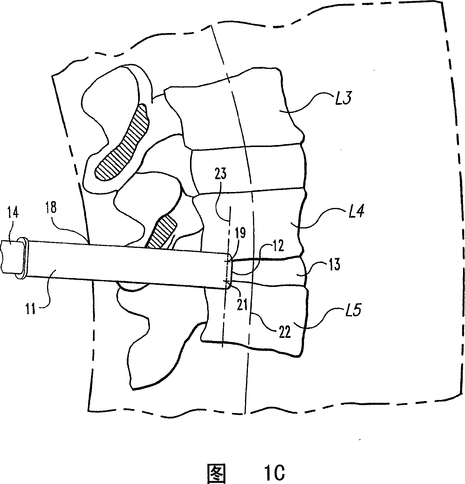
[0020] Referring to Figures 1A-1C, which schematically illustrate the lumbar vertebrae L3, L4 and L5, the pre-planned surgical site is at the L4-L5 junction and is accessed through a posterior approach. The tubular retractor 11 according to the illustrated embodiment of the invention is shown placed in a suitable position with its distal end 12 contacting the layers L4 and L5 of the intervertebral disc 13 at t...


PUM


Abstract

Two groups of orderly placed tissue expanders which are oriented to become axial lines are positioned in a plane parallel to a vertebral axis, the last non-circular expander encloses the two groups of expanders, then a non-circular tubular retractor provides a working channel extended along the longitudinal direction of the vertebra, therefore an operation can enter into the larger area of a surgical site from the smallest cut.

Description

technical field [0001] The present invention relates to instruments and methods for performing surgical tissue distraction using minimally invasive procedures. Background technique [0002] Performing traditional surgery on pathology located in vivo can cause considerable trauma to the intervening tissues. These procedures typically require a long incision, extensive muscle stripping, extensive tissue retraction, and removal of nerves and vessels within the tissue. These procedures can require an operating room, several hours of time, and several weeks of post-operative recovery time due to the damage to tissue during the surgical procedure. In some cases, these traumatic procedures cause permanent scarring and even more severe pain requiring surgical intervention. [0003] US Patent No. 5,792,044 to Kevin T. Foley et al. provides some in-depth background information on percutaneous procedures. Figures 10a to 10i and the following portion of column 10, line 11 of this pat...

Claims


Application Information

Patent Timeline
Patent Type & Authority Patents(China)
IPC IPC(8): A61B17/02A61B17/34A61B17/17
CPCA61B17/3421A61B2017/3445A61B2017/3447A61B17/1757A61B17/02A61B17/56
Inventor T·E·罗姆三世W·B·奴尔
Owner WARSAW ORTHOPEDIC INC
Why Eureka
Try Eureka