
Electronics housing with integrated thermal dissipater

A radiator and housing technology, applied in the field of electronic housings of measuring transducers, can solve the problems of defects and high connection costs, and achieve the effect of reducing uneven temperature distribution

Inactive Publication Date: 2007-10-31
EHNDRESS KHAUZER GMBKH KO KG
View PDF4 Cites 0 Cited by
  • Summary
  • Abstract
  • Description
  • Claims
  • Application Information

AI Technical Summary

Problems solved by technology

The above arrangement is disadvantageous in terms of the small cross-section of the fins perpendicular to the direction of the fins and the reduction of the additional holes
In addition, the construction of the thermally conductive switch and the connection of the thermally conductive switch to the thermal mass are expensive

Method used


Image

  • Electronics housing with integrated thermal dissipater
  • Electronics housing with integrated thermal dissipater
  • Electronics housing with integrated thermal dissipater

Examples


Embodiment Construction

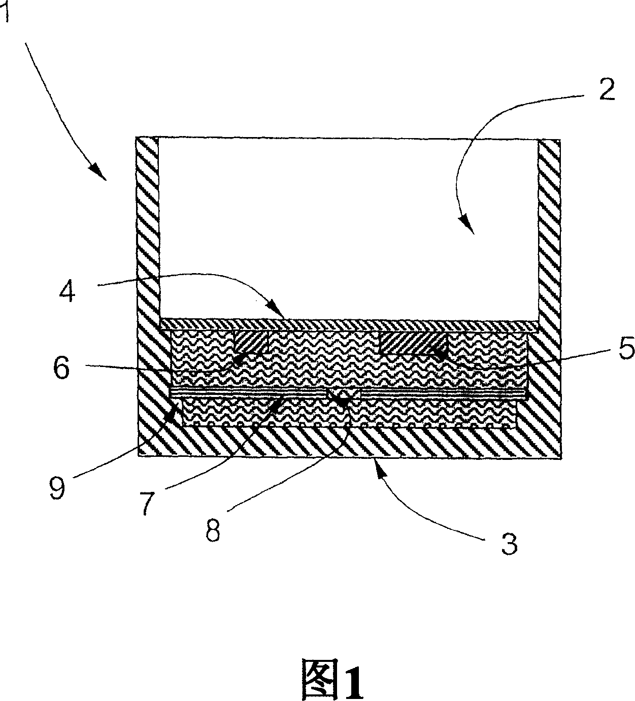
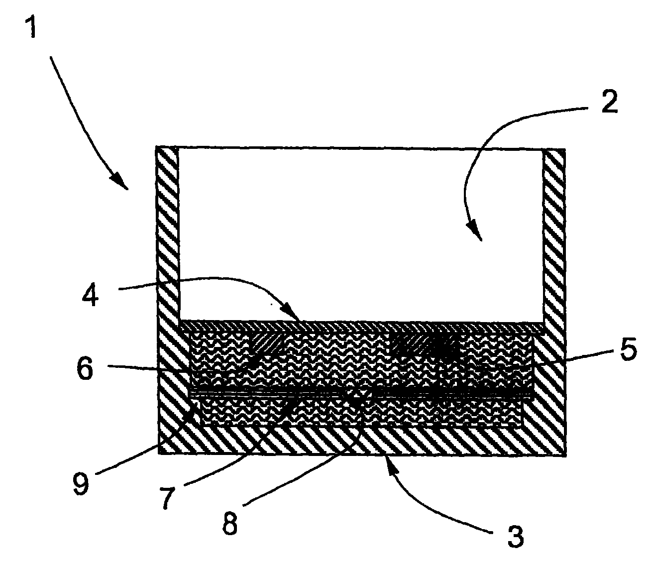
[0017] The measuring transducer housing 1 shown in FIG. 1 encloses an interior 2 on which a printed circuit board 4 is arranged parallel to the first wall 3 of the housing 1 . The first wall can be, for example, the end face of the cylindrical housing 1 . On the first surface of the circuit board 4 facing the first wall, electrical or electronic components 5, 6 are arranged, and in order to avoid overheating of the electronic components 5, 6, the heat generated during operation must be diverted away.

[0018] To this end, at least the interior 2 in the section between the circuit board 4 and the first wall 3 is filled with a filler 10 , preferably Silgel. A heat sink 7 is built into the filler, which is arranged substantially parallel to the circuit board 4 . The position of the heat sink 7 spaced apart from the circuit board and the first wall 3 is defined in structural form by a stop 9 on which the edge of the heat sink is placed.

[0019] The heat sink 7 is preferably a m...


PUM


Abstract

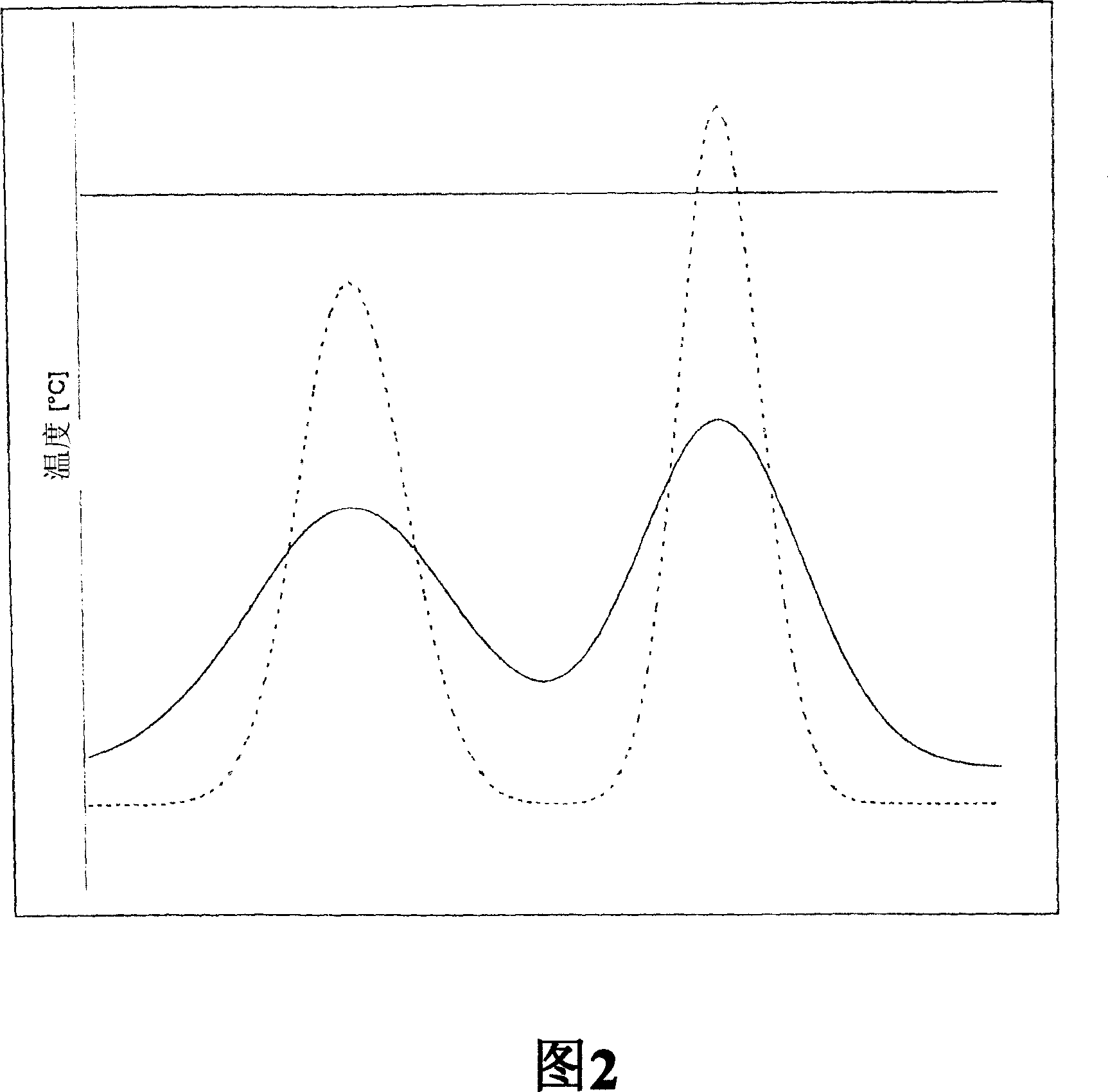
An electronics housing with a circuit board in the interior of the electronics housing, fitted with electronics components on at least one first surface, said first surface facing a first wall of the electronics housing and the interior is filled with a thermally conducting sealing mass, at least between the first surface of the circuit board and the first wall. According to the invention, local overheating on the external housing surfaces may be avoided whereby a planar heat dissipater is arranged in the sealing mass, between the circuit board and the first wall, which has a higher specific heat conductivity than the sealing mass, whereby inhomogeneous temperature distributions along the surfaces of the first wall are reduced.

Description

technical field [0001] The invention relates to electronic housings, in particular electronic housings for measuring transducers. Background technique [0002] When designing electronic instruments, it is important to avoid maximum temperature values ​​as much as possible in order to ensure the reliability of electronic switching circuits. Especially in explosion-proof applications, it should be ensured that the waste heat generated by the electronic components is diverted so that no surface of the instrument can reach the ignition temperature. [0003] The prior art discloses heat sinks produced by pressure technology on circuit boards, of which Kramer et al. gave an overview in their presentation Nr. The heat path to the circuit board requires a plane, which limits the integration of electrical or electronic components on the circuit board. [0004] European patent Nr. 0 920 789 B1 discloses heat sinks, which basically have a planar metal heat sink arranged in parallel t...

Claims


Application Information

Patent Timeline
Patent Type & Authority Patents(China)
IPC IPC(8): H05K7/20H05K5/06H05K3/28
CPCH05K7/20463H05K3/284H05K5/064
Inventor 英戈·布施克
Owner EHNDRESS KHAUZER GMBKH KO KG
Learn More