Eureka AIR delivers breakthrough ideas for toughest innovation challenges, trusted by R&D personnel around the world.

Shearing head for hair clippers

A cutting device and technology for shaving heads, which can be used in metal processing and other directions, and can solve problems such as large shaving heads

Inactive Publication Date: 2007-11-07
BRAUN AG
View PDF4 Cites 0 Cited by
  • Summary
  • Abstract
  • Description
  • Claims
  • Application Information

AI Technical Summary

Problems solved by technology

In order to reduce the possibility of this situation taking place with the previously known shaving heads, it is necessary to considerably extend the length of the cutting edge, i.e. the tines or grooves, which results in a larger size of the shaving head

Method used


Image

  • Shearing head for hair clippers
  • Shearing head for hair clippers
  • Shearing head for hair clippers

Examples


Embodiment Construction

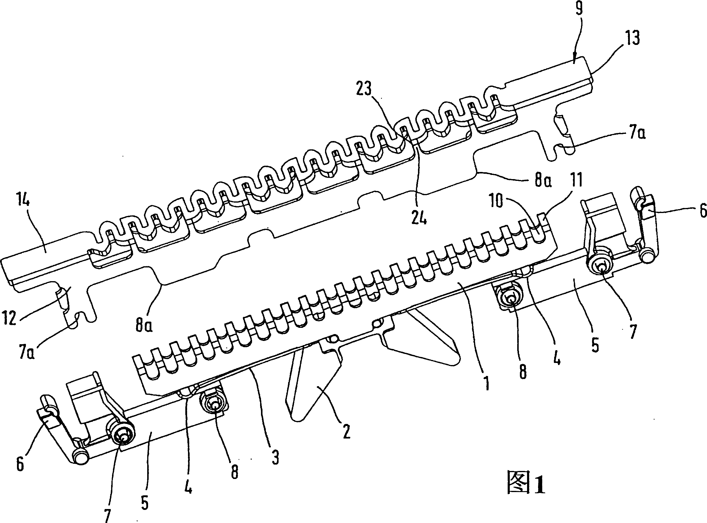
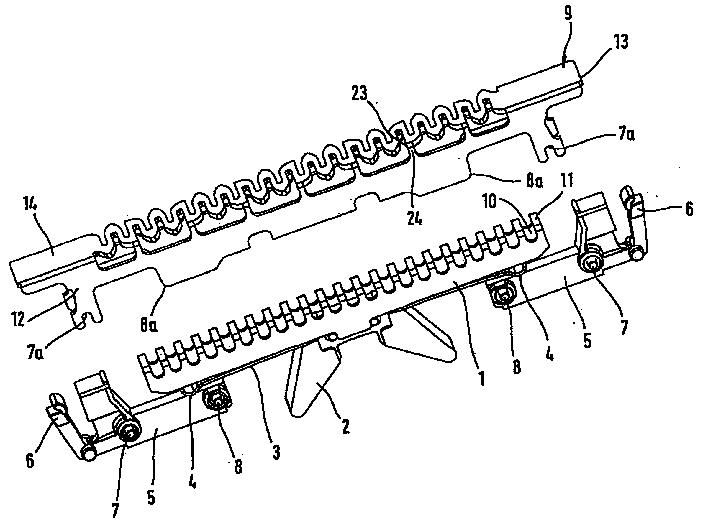
[0015] The shaving head shown in Figure 1 has a lower cutter 1 with a coupling part 2 for connection to an electric drive mechanism (not shown) of the hair cutting device, for example in the form of a transmission eccentric shaft or an oscillating bridge pieces. By means of a drive mechanism, the lower cutter 1 can be driven in an oscillating manner in the transverse direction. Also fixed to the lower cutter 1 is a biasing spring 3 configured as a bent leaf spring whose ends 4 are supported on corresponding supports 5 . The supporting body 5 has a corresponding positioning handle 6, which is suitable for being locked in a housing not shown in the figure or a part connected with the housing, especially in the movable frame of the shaving system of the hair cutting device. Each end of the support body 5 has an outer weld point 7 and an inner weld point 8 respectively, by means of which it can be welded to a corresponding mating surface 7a and 8a on the outer cutter 9 respective...


PUM


Abstract

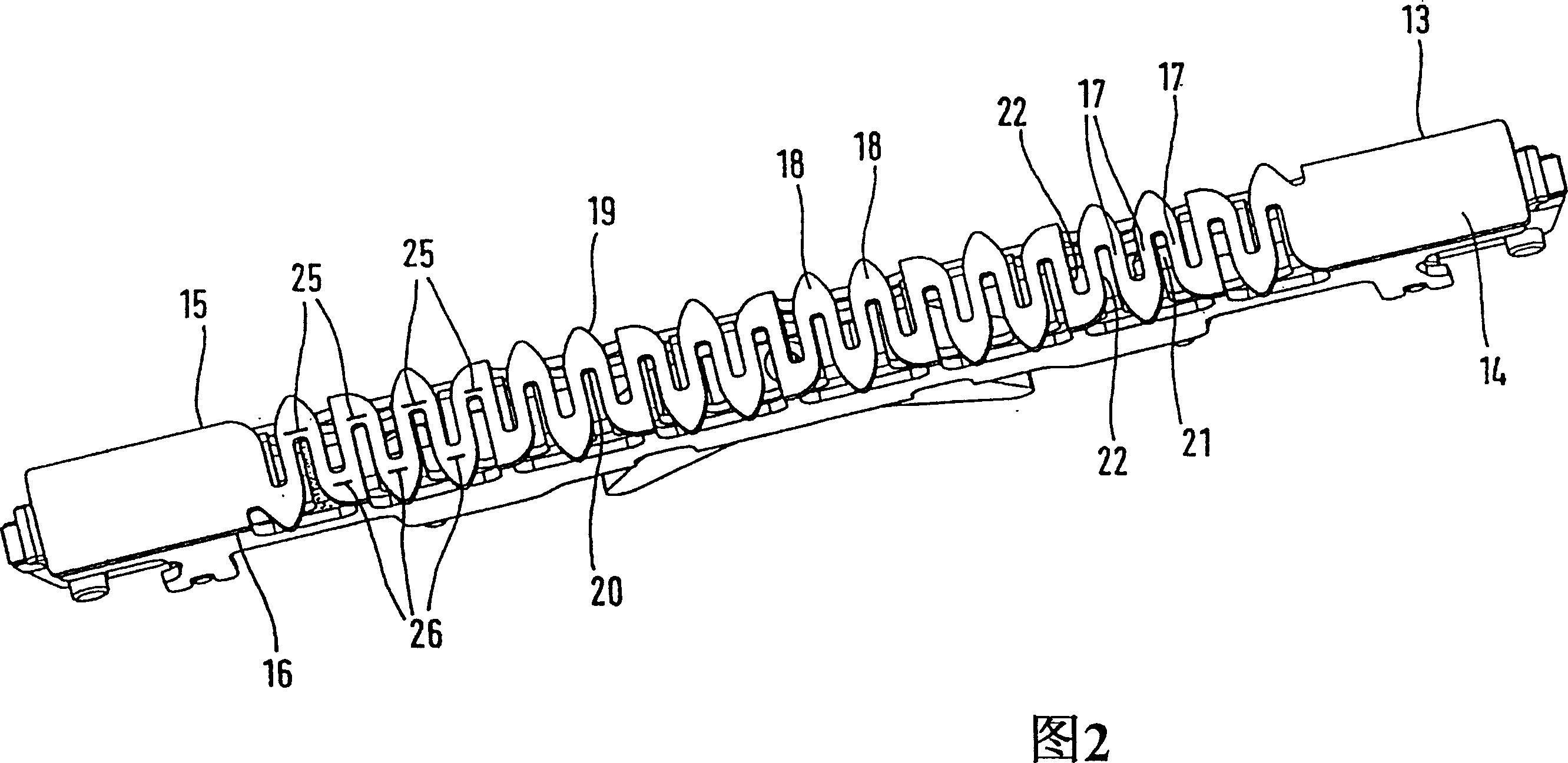
The invention is directed to a shaving head for a hair cutting apparatus, with at least one outer cutter and at least one undercutter associated therewith and having cutting edges, said cutters being movable relative to one another by a drive mechanism, with the outer cutter having an engagement surface comprised of bars and slots, which slots are open at least towards one of two lateral boundary lines of the engagement surface, said boundary lines defining the width of the engagement surface, wherein the bars are shaped in a meandering, sinusoidal or serpentine configuration extending to and fro between the two opposite lateral boundary lines of the engagement surface.

Description

technical field [0001] The invention relates to a shaving head of a hair cutting device, having at least one outer cutter and at least one lower cutter coupled thereto and having a cutting edge, said cutters being movable relative to each other by means of a drive mechanism; The cutter has an engaging surface comprising a barrier and a groove, the groove opening towards at least one of two transverse boundaries of the engaging surface, said boundary defining the width of the engaging surface. Background technique [0002] Such a shaving head is known from DE 43 12 060 C1 and is used, for example, as a long hair cutter in combination with a short hair cutter assembly of an electric dry shaving apparatus. The preferred application is to be integrated as an intermediate cutter between two shaving foils. Previously known shaving heads have an undercutter comprising a U-shaped blade having a plurality of grooves and driven to oscillate in a transverse direction. The blade is ur...

Claims


Application Information

Patent Timeline
IPC IPC(8): B26B19/04B26B19/14
CPCB26B19/042
Inventor 沃尔夫冈·弗兰克维尔纳·夏切克托尔斯滕·皮斯克斯特凡·菲尔斯特安德烈亚斯·彼得
Owner BRAUN AG
Why Eureka
Eureka Blog
Learn More