Piezoelectric type microdroplet sprayer with membrane

A spray device, piezoelectric technology, applied in printing and other directions, can solve the problems of limited compression effect of piezoelectric elements, inability to generate high pressure, fluid particles are not easy to micronize, etc., to avoid corrosive fluid damage, wide application range, The effect of increasing the fluid compression pressure

Inactive Publication Date: 2007-11-21
IND TECH RES INST
View PDF5 Cites 0 Cited by
  • Summary
  • Abstract
  • Description
  • Claims
  • Application Information

AI Technical Summary

Problems solved by technology

However, in the existing designs, the gap of the cavity is usually much larger than the vibration amplitude of the piezoelectric element, so when the piezoelectric element vibrates, only a small volume change of the cavity is caused, so the compression of the piezoelectric element The effect is limited, and high pressure cannot be generated, so that the aperture of the orifice plate cannot be too small, so the fluid particles ejected by the existing micro-droplet ejection device of this type are not easy to be atomized

Method used


Image

  • Piezoelectric type microdroplet sprayer with membrane
  • Piezoelectric type microdroplet sprayer with membrane
  • Piezoelectric type microdroplet sprayer with membrane

Examples


Embodiment Construction

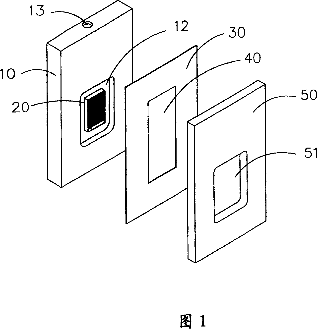
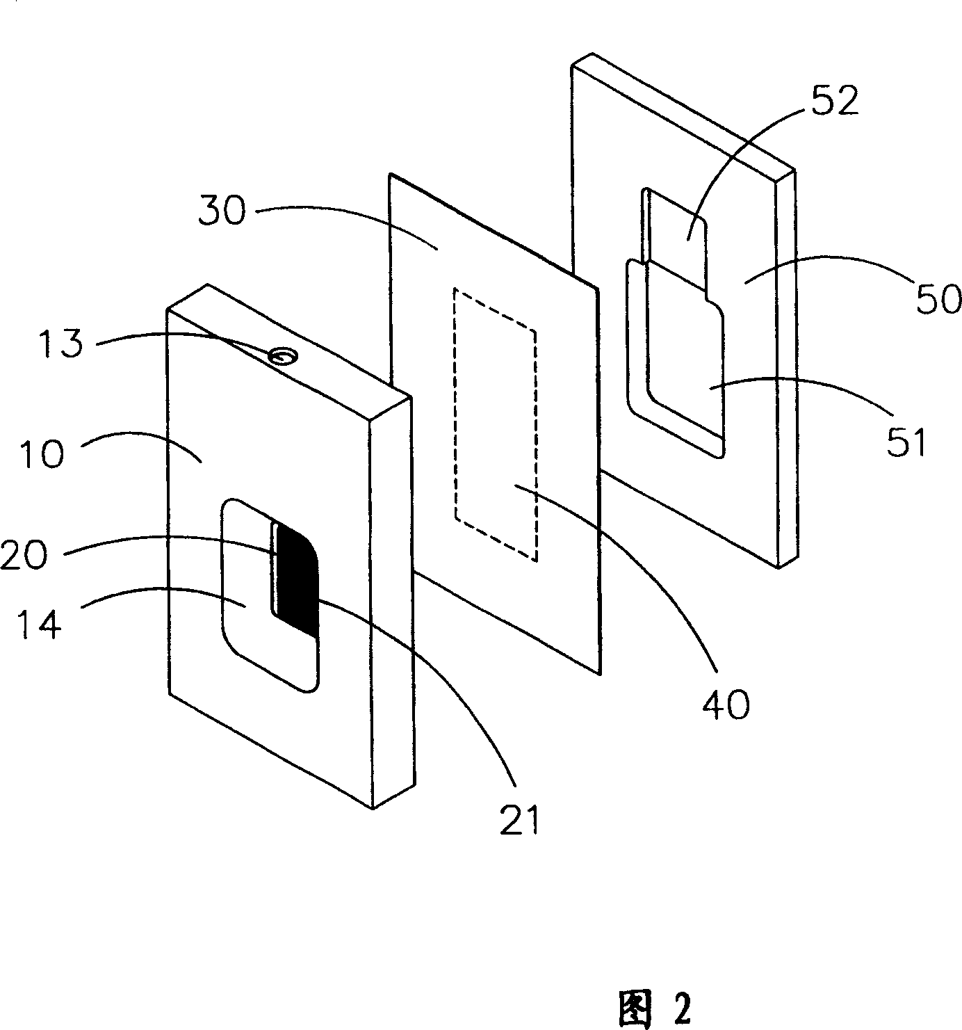
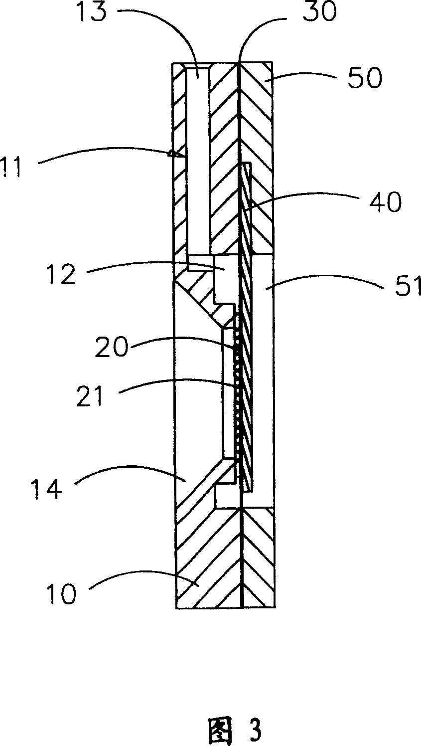
[0026] As shown in FIGS. 1 and 2 , the present invention includes an orifice seat 10 , an orifice plate 20 , a diaphragm 30 , a piezoelectric plate 40 and a piezoelectric plate holder 50 .

[0027] The nozzle hole seat 10 is provided with an installation hole 14 for the nozzle hole plate 20 to be installed in the installation hole 14 . On the nozzle hole seat 10, a fluid passage 11 is provided, and the fluid passage 11 includes a cavity 12 surrounding the surrounding area of ​​the nozzle hole plate 20 and an inlet channel 13 connected from the cavity 12 to the outside of the nozzle hole seat 10. The flow channel 13 can guide the fluid from the outside of the nozzle hole seat 10 into the cavity 12 , and allow the fluid to enter the gap between the nozzle hole plate 20 and the diaphragm 30 from around the nozzle hole plate 20 .

[0028] The orifice plate 20 is a flat plate, on which several tiny orifices 21 are arranged densely, for the fluid to be sprayed out from the orifices ...


PUM


Abstract

The present invention relates to a piezoelectric microdroplet jet device with diaphragm. Said device includes jet orifice seat, jet orifice plate placed on the jet orifice seat, diaphragm, piezoelectric plate and piezoelectric plate supporting seat which is used for placing piezoelectric plate and whose four edges are fitted with jet orifice seat; on the jet orifice seat a cavity body and a fluid channel capable, of guiding fluid into said cavity body are set; on the jet orifice plate several small jet orifices are set; said diaphragm is placed between jet orifice plate and piezoelectric plate, and the periphery of the diaphragm is fitted between the jet orifice seat and piezoelectric plate supporting seat; at least a portion of piezoelectric plate is connected with diaphragm, and can be used for driving said diaphragm to produce vibration.

Description

technical field [0001] The invention belongs to a spraying device, in particular to a piezoelectric micro-droplet spraying device with a diaphragm. Background technique [0002] In recent years, micro-electro-mechanical technology has made great progress due to the substantial progress in process technology and a large amount of resources invested in research. Among them, the development of micro-injection devices has become the product and technology with the most fruitful research results in micro-electromechanical systems due to the large number of commercial applications of ink-jet printers, and because micro-injection devices can accurately control the flow rate of a small amount of liquid and The efficacy of flow rate, therefore, is more widely used in fields such as biotechnology and medical treatment, micro-coating or quantitative control devices, and indoor air fragrance generating devices. [0003] Existing micro-injection devices can be mainly divided into therma...

Claims


Application Information

Patent Timeline
Patent Type & Authority Patents(China)
IPC IPC(8): B41J2/045B41J2/01
Inventor 高天和彭毓莹简金品
Owner IND TECH RES INST
Why Eureka
Try Eureka