Method for producing a machining segment for an abrasive machining tool

a technology of machining segment and abrasive, which is applied in the direction of adding to the production process, improving process efficiency, and increasing energy efficiency, etc. it can solve the problems of reducing the lifetime of the machining segment, material particles falling out prematurely, and damage to the mold, so as to improve the suit the flowability of the second metallic powder material is higher, and the effect of rapid flow

Active Publication Date: 2021-04-29
HILTI AG
View PDF0 Cites 0 Cited by
  • Summary
  • Abstract
  • Description
  • Claims
  • Application Information

AI Technical Summary

Benefits of technology

[0028]Preferably, the second metallic powder material used is a metallic powder material which is at least readily flowing. More preferably, the second metallic powder material used is a metallic powder material which is free-flowing. An at least readily flowing second metallic powder material is suitable for the layer-by-layer construction of the neutral zone within the method of the invention. The higher the flowability of the second metallic powder material, the better the suitability of the second metallic powder material for the layer-by-layer construction of the neutral zone within the method of the invention for production of a machining segment.
[0029]Preferably, the second metallic powder material used is a metallic powder material compressible at a maximum pressure of 1250 MPa to an average density δ of greater than 90% of the theoretical density δth. At average densities δ of greater than 90% of the theoretical density δth, the porosity ϕ of the neutral zone of the machining segments is below 10% by volume. The lower the porosity of the neutral zone of the machining segments, the higher the breakout resistance of the machining segments and hence the robustness of the machining tools.
[0030]More preferably, the second metallic powder material used is a metallic powder material compressible at a maximum pressure of 1250 MPa to an average density δ of greater than 93% of the theoretical density δth. At average densities δ of greater than 93% of the theoretical density δth, the porosity ϕ of the machining segments is below 7% by volume. The lower the porosity of the neutral zone of the machining segments, the higher the breakout resistance of the machining segments and hence the robustness of the machining tools.

Problems solved by technology

The pores distributed in the machining segment do not offer sufficient holding forces for the hard material particles in the sintered metallic powder material, and so the hard material particles are loosened during machining, the result of which is that the hard material particles fall out prematurely and the lifetime of the machining segments is reduced.
The known method has the disadvantage that the hard material particles are arranged in random distribution in the metallic powder material and can protrude from the surface of the compacted green body.
Hard material particles that protrude from the surface of the compacted green body can damage the mold on compaction of the green body to the final geometry.
At compression pressures exceeding 850 MPa, the molds have elevated wear, which increases the mold costs in production and can make the production of the machining segments uneconomic.

Method used


Image

  • Method for producing a machining segment for an abrasive machining tool
  • Method for producing a machining segment for an abrasive machining tool
  • Method for producing a machining segment for an abrasive machining tool

Examples


first embodiment

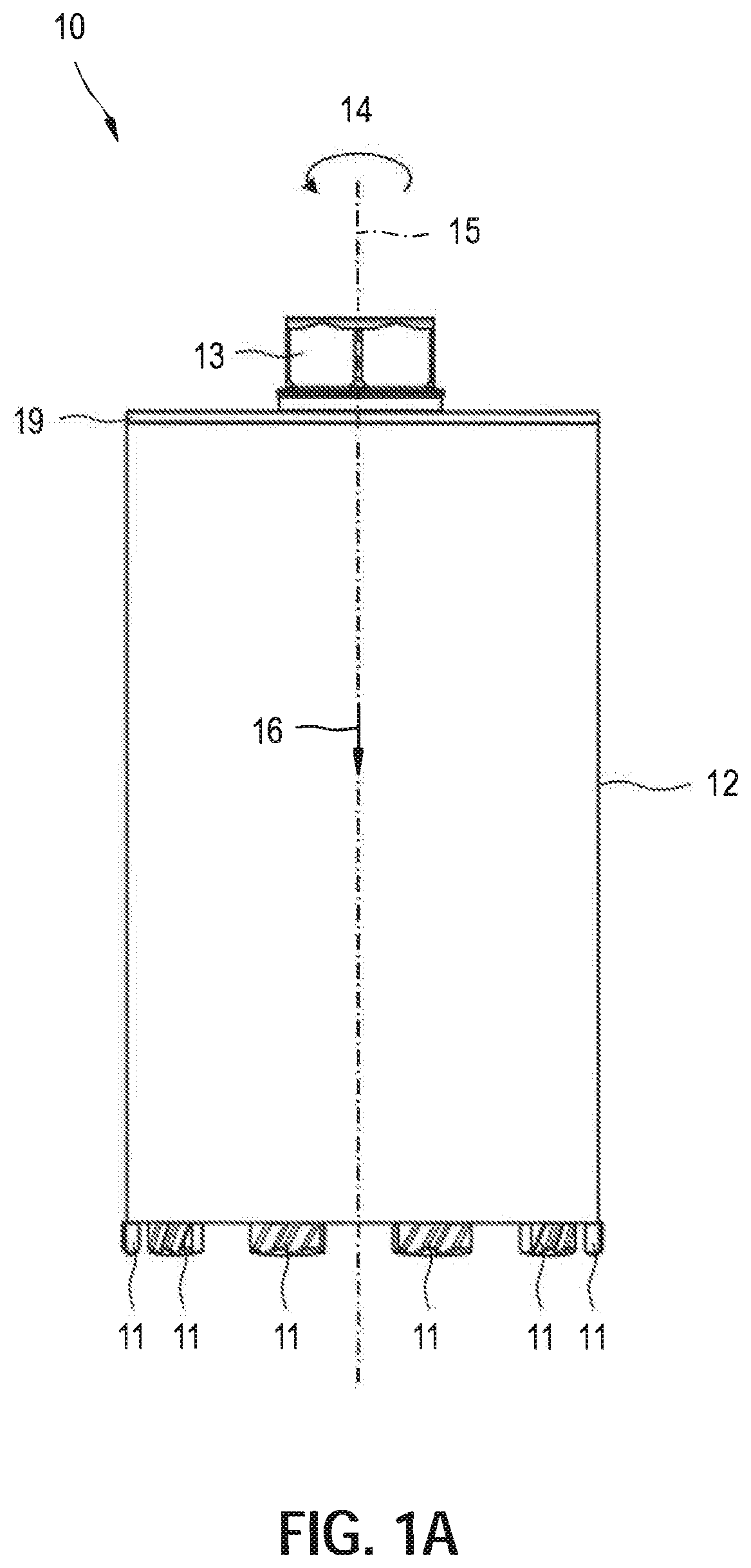
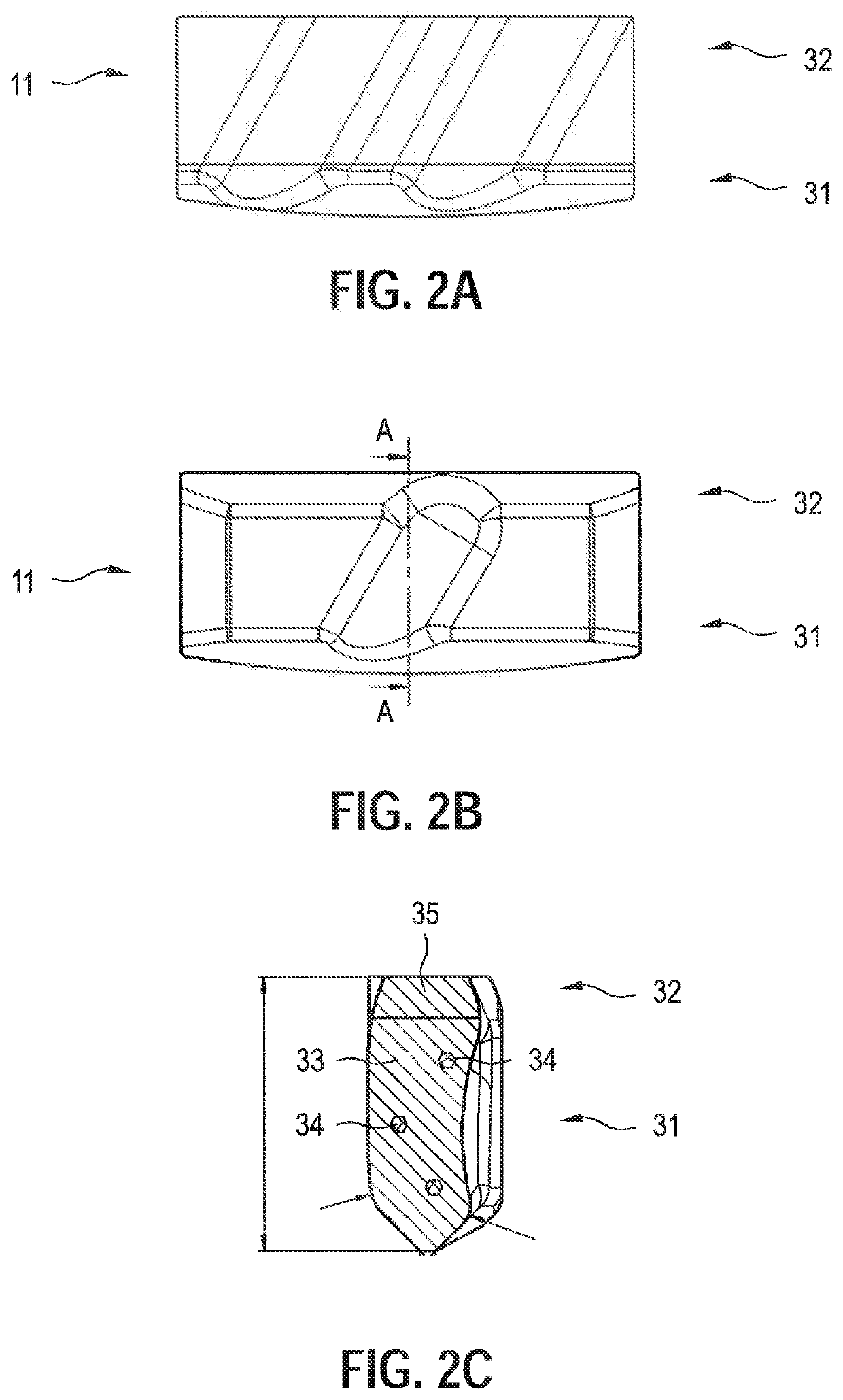
[0045]FIGS. 2A-C show the drill segment 11 of the drill bit 10 of FIG. 1A in a view of the outside of the drill segment 11 (FIG. 2A), in a view of the inside of the drill segment 11 (FIG. 2B) and in a section along the section line A-A in FIG. 2B (FIG. 2C). In the machining of a workpiece with the drill bit 10, the outside of the drill segment 11 faces the drill hole and the inside of the drill segment 11 faces the drill core. The drill segment 11 of the drill bit 10 forms a machining segment which is produced by means of the method of the invention for producing a machining segment.

[0046]Since the drill segment 11 is welded to the drill shaft 12, the drill segment 11 is constructed from a machining zone 31 and a neutral zone 32 that are cohesively bonded by sintering. In the case of drill segments that are connected to the drill shaft 12 by soldering, for example, the neutral zone 32 can be dispensed with. The machining zone 31 has been produced from a first metallic powder materia...

second embodiment

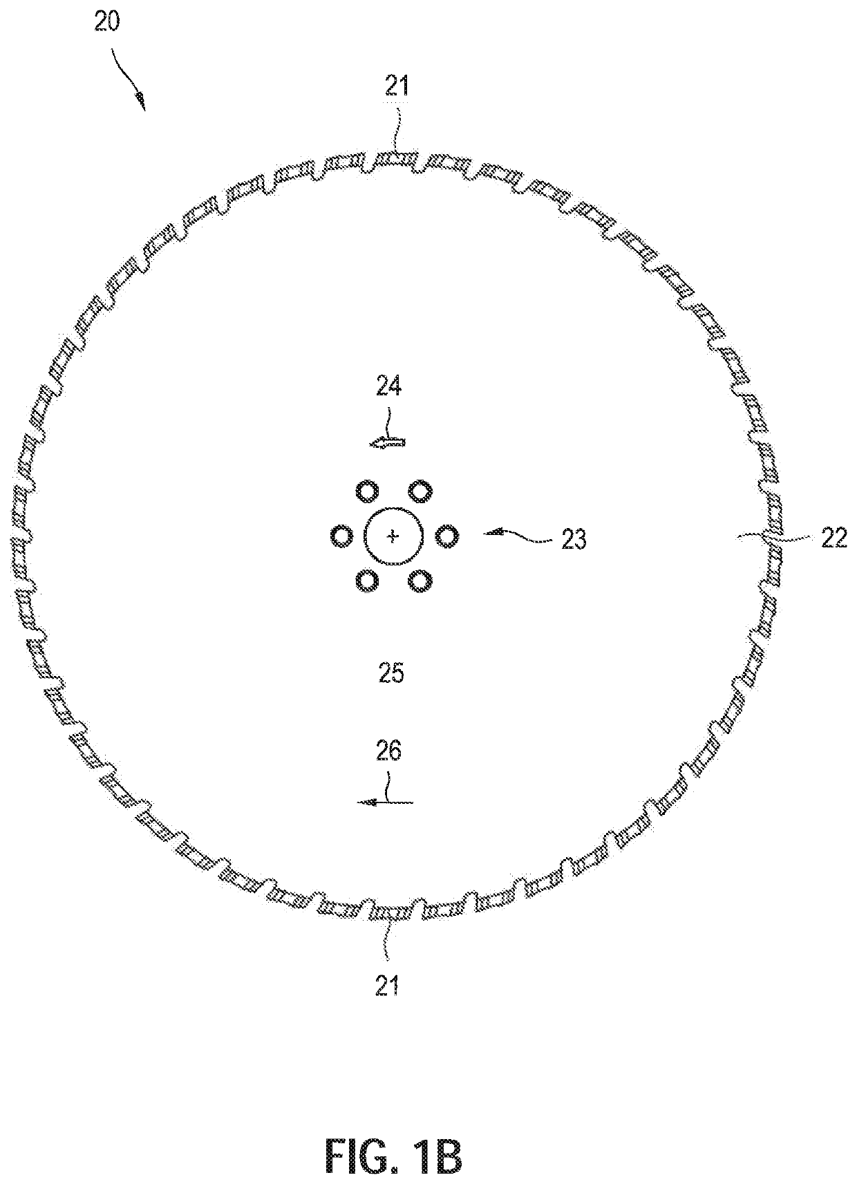
[0048]FIGS. 3A-C show the saw segment 21 of the saw blade 20 of FIG. 1B in a three-dimensional view of the saw segment 21 (FIG. 3A), in a view of a first side of the saw segment 21 (FIG. 3B) and in a view of a second side of the saw segment 21 (FIG. 3C). The saw segment 21 of the saw blade 20 forms a machining segment which is produced by means of the method of the invention for producing a machining segment.

[0049]Since the saw segment 21 is welded to the main body 22, the saw segment 21 is constructed from a machining zone 41 and a neutral zone 42 that are cohesively bonded by sintering. In the case of saw segments that are connected to the main body 22 by soldering, for example, the neutral zone 42 can be dispensed with. The machining zone 41 has been produced from a first metallic powder material 43 and hard material particles 44, and the neutral zone 42 has been produced from a second metallic powder material 45, where the neutral zone 42 is free of hard material particles 44.

[0...


PUM

PropertyMeasurementUnit
lateral distanceaaaaaaaaaa
compression pressureaaaaaaaaaa

Abstract

A method of producing a machining segment, in which a green body (51) is constructed from a machining zone (54), wherein the machining zone (54) is produced from a first metallic powder material (56) and hard material particles (58), the green body (51) is compacted under pressure with a compression pressure to result in a compact body and the compact body is sintered thermally at a sintering temperature to result in the finished machining segment, wherein the machining zone (54) is produced by layer-by-layer application of material layers of the first metallic powder material (56) and particle layers of the hard material particles (58), wherein the hard material particles (58) in one particle layer are placed into the previously applied material layer of the first metallic powder material (56).

Description

[0001]The present invention relates to a method of producing a machining segment for an abrasive machining tool.BACKGROUND[0002]Abrasive machining tools such as drill bits, saw blades and grinding disks include machining segments that are secured on a tubular or disk-shaped main body, with bonding of the machining segments to the main body, for example, by welding, soldering or adhesion. Depending on the machining method of the abrasive machining tool, the machining segments are referred to as drill segments, saw segments or grinder segments and are summarized by the term “machining segments”.[0003]Machining segments have a machining zone constructed from a metallic powder material and hard material particles. The machining of a substrate is effected by means of the hard material particles distributed in the metallic powder material. Machining segments that are to be welded to the tubular or disk-shaped main body of the abrasive machining tool are constructed from the machining zone...

Claims


Application Information

Patent Timeline
Patent Type & Authority Applications(United States)
IPC IPC(8): B22F7/02B22F3/16B22F5/00
CPCB22F7/02B22F3/16B22F2005/001B22F2304/10B22F5/00B22F7/06B22F10/10Y02P10/25B23P15/28
Inventor SONDEREGGER, MARCELMUELLER, MATTHIASSCHAEFER, HEIKO
Owner HILTI AG
Why Eureka
Try Eureka