
End-clearance-free piston ring provided with positioning groove

A piston ring, no end gap technology, applied in the field of piston rings, can solve the problems of increasing fuel consumption, reducing the compression pressure of internal combustion engines, reducing the power of internal combustion engines, etc., and achieving the effects of reducing emissions, reducing emissions, and improving power.

Active Publication Date: 2011-11-09
杨应捷
View PDF5 Cites 1 Cited by
  • Summary
  • Abstract
  • Description
  • Claims
  • Application Information

AI Technical Summary

Problems solved by technology

It will also reduce the compression pressure of the internal combustion engine, increase fuel consumption, and reduce the power of the internal combustion engine

Method used


Image

  • End-clearance-free piston ring provided with positioning groove
  • End-clearance-free piston ring provided with positioning groove
  • End-clearance-free piston ring provided with positioning groove

Examples


Embodiment Construction

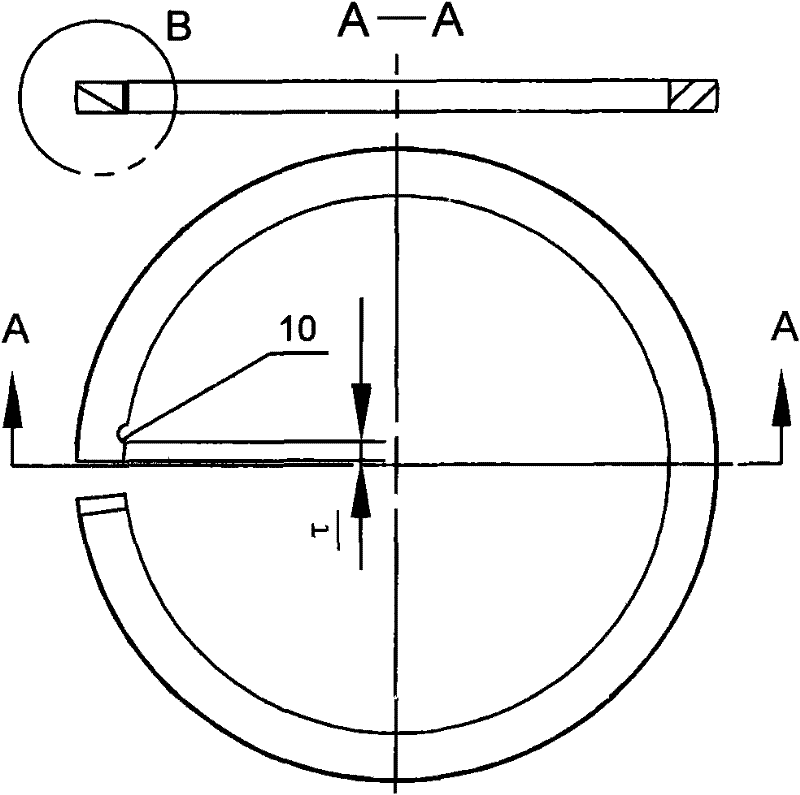
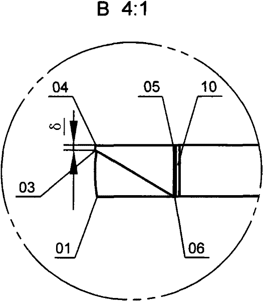
[0025] figure 1 , figure 2 , Figure 13 , Figure 14 , Figure 15 and Figure 16 The comparison shows that the piston ring changes from the natural state to the working state where the opening is closed by being placed in the cylinder or in the ring gauge. End-to-end lap length for fully sealed diagonal cutouts for backlash-free piston rings shown T , the expansion gap required for heating s , the distance between the cylindrical surface of the piston ring and its end surface τ Establish a small circular arc positioning groove 10, or at the other end from its end face τ Establish a small circular arc positioning groove 10 such as Figure 18 shown. Section line I-I symmetrically passes through the lap length T and piston ring shaft. lap length T Add expansion gap s is the dimension from the shoulder face to the boss face of the end face. Such as figure 2 , Figure 14 The diagonal line shown is a small distance from point 04 along the projected line of the ou...


PUM


Abstract

The invention discloses a fully-sealed piston ring provided with a positioning groove. The diagonal incision of the piston ring has no end clearance. The outside diameter perimeter is longer than the inside diameter perimeter of a cylinder, and the length of the excess part is equal to the lapped size of ports. A first end-clearance-free piston ring has a barrel surface or a cylindrical surface, and a tangential plane is defined by the intersection point of projection lines of an excircle surface and an upper end surface of an axial cross section of the piston ring, and a diagonal line from a point, delta distance from the projection line of the excircle surface, to the intersection point of projection lines of an inner cylindrical surface and a lower end surface. A second end-clearance-free piston ring is a taper-face ring which consists of an upper taper face and a lower cylindrical surface with the height of theta, and a tangential plane is defined by the intersection point of the projection lines of an outer cylindrical surface and a lower end surface of an axial cross section of the piston ring, and a diagonal line from a point, delta distance from the projection line of the outer cylindrical surface, to the intersection point of projection lines of the inner cylindrical surface and the upper end surface. The diagonal line tangential plane is a plane surface or a cambered surface. Two end heads of the piston ring consist of an upper four-side wedge-shaped edge, a lower triangular edge, an upper triangular edge, a lower four-side wedge-shaped edge, an end head surface and an end shoulder surface respectively. The projection lines of the end head surface and the end shoulder surface are parallel with an axial line at equal distance or parallelly intersect with the axial line on the axial line respectively. A small circular arc positioning groove, tau distance from the end face and is opened at any end of the two end heads.

Description

technical field [0001] The invention relates to a piston ring with a diagonal cut structure that is fully sealed and equipped with positioning grooves to prevent adjacent piston rings from matching for internal combustion engines and air compressors, and has a wear compensation function, which is called endless with positioning grooves Gap piston ring. Background technique [0002] In the prior art, the piston rings of internal combustion engines and air compressors are in the shape of straight cuts, and there are very few oblique cuts and stepped cuts without positioning grooves. Straight cut piston rings are the most widely used. It uses two to four air-tight rings, and the adjacent piston rings are staggered by 120°-180° on the piston with straight-edge cuts to form a labyrinth sealing structure to achieve air-tightness. According to the different designs of the internal combustion engine, the general gasoline engine has two air-tight rings, and the diesel engine has tw...

Claims


Application Information

Patent Timeline
Patent Type & Authority Applications(China)
IPC IPC(8): F02F5/00F04B39/00F16J9/16F16J9/24
Inventor 杨应捷杨惜景
Owner 杨应捷
Learn More