A self-balancing geometric beam-splitting method and quantum true random code generating apparatus

A self-balancing and scoring technology, applied in the field of optics and secure communications, which can solve the problems of inconsistent quantum efficiency and aging performance of detectors, consistent detector performance, and uneven proportions.

Active Publication Date: 2007-11-28
ANHUI QASKY QUANTUM SCI & TECH CO LTD
View PDF3 Cites 0 Cited by
  • Summary
  • Abstract
  • Description
  • Claims
  • Application Information

AI Technical Summary

Problems solved by technology

This setup is affected by factors such as the splitting ratio of the beam splitter, the quantum efficiency of the two detectors, and the inconsistency in aging performance
Due to process limitations, it is actually difficult to strictly achieve the beam splitting ratio of the beam splitter at 1:1; the performance of the detector cannot be completely consistent, even if the system can be adjusted to a balanced state by other means, but as time goes by , due to the inconsistent aging performance of the device, the pollution of the optical path, etc. will cause the system to be unbalanced again, so that the ratio of 0 and 1 in the random code output by the device is uneven, affecting the quality of the random number

Method used


Image

  • A self-balancing geometric beam-splitting method and quantum true random code generating apparatus
  • A self-balancing geometric beam-splitting method and quantum true random code generating apparatus
  • A self-balancing geometric beam-splitting method and quantum true random code generating apparatus

Examples


Embodiment 1

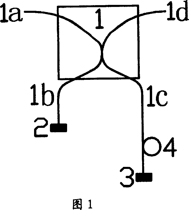
[0037] Embodiment 1: A self-balancing equal beam splitting device composed of an optical fiber beam splitter and a mirror

[0038] In this embodiment, a polarization-independent 50:50 fiber optic beam splitter and reflectors are used to form a self-balanced equal-ratio beam device. The ends of the two ports (1b) and (1c) of ) are respectively placed with mirrors (2) and (3), and an optical delayer (4) is placed on the port (1c).

[0039]When using this device, the incident light can be polarized light or unpolarized light. The incident light can be input from the port (1a) of the optical fiber splitter (1) and output from the port (1d), and can also be input from the port (1d) of the optical fiber splitter (1) and output from the port (1a). The input photons are split into reflected light and transmitted light according to the reflectivity and transmittance determined by the beam splitting ratio. The reflected light propagates through the port (1b), is reflected by the mirror...

Embodiment 2

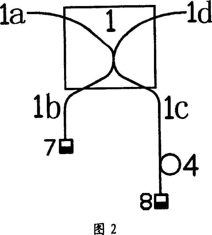
[0041] Embodiment 2: A self-balancing equal beam splitting device composed of an optical fiber beam splitter and a Faraday reflector

[0042] In this embodiment, a polarization-independent 50:50 optical fiber beam splitter and a Faraday reflector are used to form a self-balanced equal beam splitter. Fig. 2 shows a schematic diagram of the self-balanced equal beam splitter of this embodiment: the optical fiber beam splitter ( 1) Faraday reflectors (7) and (8) are placed at the ends of the two ports (1b) and (1c) respectively, and an optical delayer (4) is placed on the port (1c).

[0043] When using this device, the incident light can be polarized light or unpolarized light. The incident light can be input from the port (1a) of the optical fiber splitter (1) and output from the port (1d), and can also be input from the port (1d) of the optical fiber splitter (1) and output from the port (1a). The incident light is split into reflected light and transmitted light, the reflected...

Embodiment 3

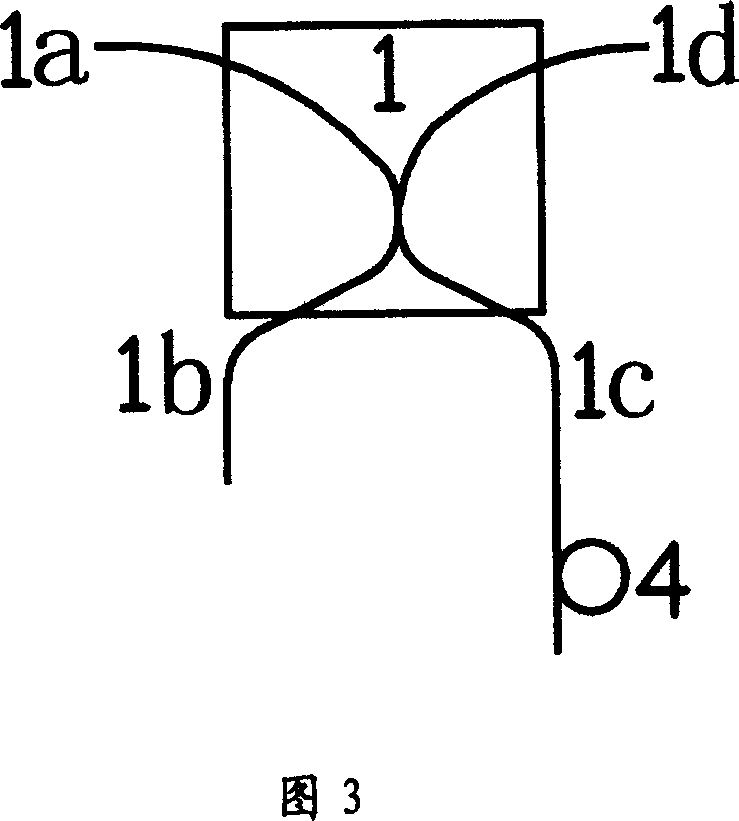
[0044] Embodiment 3: A self-balanced equal-ratio beam splitter composed of optical fiber end face reflection

[0045] In this embodiment, a polarization-independent 50:50 optical fiber beam splitter is used and the self-balanced equal-ratio beam splitter is composed of fiber end face reflections. Figure 3 shows a schematic diagram of the self-balanced equal-ratio beam splitter of this embodiment: fiber beam splitter An optical delayer (4) is placed on the port (1c) of (1).

[0046] When using this device, the incident light can be polarized light or unpolarized light. The incident light can be input from the port (1a) of the optical fiber splitter (1) and output from the port (1d), and can also be input from the port (1d) of the optical fiber splitter (1) and output from the port (1a). The incident light is split into reflected light and transmitted light. The reflected light propagates through the port (1b), is reflected by the fiber end face of the port (1b) and returns to ...


PUM


Abstract

The present invention is self-balancing equiratio light beam splitting method and device and single probe quantum true random code generator constituted therewith, and features the connection of clock circuit output to the single photon source input and the clock input of the data processing circuit, the connection of the single photon detector to data input of the data processing circuit, the connection of single photon source output to the self-balancing equiratio light beam splitter input, the connection of the self-balancing equiratio light beam splitter output to the single photon detector input, and the optical delay set in the reflecting or transmitting optical path after the splitter and regulated to form proper optical path difference between reflected light and the transmitted light. After reflection in the reflectors in the end of the reflecting optical path and the transmitting optical path, the light is returned along the same path and output via the other port of the splitter.

Description

Technical field: [0001] The invention belongs to the technical field of optics and secure communication, and in particular relates to a self-balanced equal-ratio beam method, an optical device, a quantum device and a quantum true random code generating device. Background technique: [0002] Random numbers can be divided into pseudo-random numbers and true random numbers. According to the introduction of "Cryptologie Contemporaine, Masson, 1992." published by French Masson Publishing House in 1992, pseudo-random numbers are random numbers generated by using complex algorithms or combinations of algorithms, but the algorithms are always regular Yes, as long as the law is known, pseudo-random numbers can be predicted in principle, so they are not random numbers in the true sense. [0003] True random numbers can be obtained by measuring the randomness of certain physical quantities. The randomness of this random number depends on the randomness of the measured physical process...

Claims


Application Information

Patent Timeline
Patent Type & Authority Patents(China)
IPC IPC(8): G06F7/58G02B27/10H04K1/00
Inventor 韩正甫吴青林莫小范郭光灿
Owner ANHUI QASKY QUANTUM SCI & TECH CO LTD
Why Eureka
Try Eureka