Integrated heating-placement hot air head

A limelight and placement technology, applied in the field of printed circuit board welding machines, can solve problems such as uneven temperature, large heat loss, slow heating/cooling, etc., to ensure placement accuracy and reliability, service life and high temperature resistance , Rapid heating/cooling effect

Active Publication Date: 2011-08-17
SHENZHEN JT AUTOMATION EQUIP CO LTD
View PDF6 Cites 0 Cited by
  • Summary
  • Abstract
  • Description
  • Claims
  • Application Information

AI Technical Summary

Problems solved by technology

[0002] The existing printed circuit board welding machine still has the following disadvantages in its hot air head: (1) Since the heating and mounting mechanism are not integrated (independently), the product is large in size and needs to occupy a certain space, and its manufacturing cost High, and affect work efficiency; (2) The temperature of the heating wire in the hot air head is uneven, the heating / cooling is slow, and the life of the heating wire is not good; (3) The existing hot air head, the hot air cannot directly act on the chip , the heat loss is large, and it is difficult to achieve infrared heating; (4) Affected by the traditional vacuum connection method, the micro-movement of the suction rod is easily affected by the vacuum connection tube, and it is difficult to guarantee the accuracy and reliability of placement; (5) The suction rod is easily affected by high temperature, resulting in bending, deformation or aging defects, which makes it difficult to ensure the placement accuracy, and even affects the service life of the suction rod; (6) The traditional heating wire is limited by the characteristics of the material itself, and its service life and durability The temperature performance is not good; (7) The structure of the whole hot air head is complicated, which is not easy to install, maintain and replace

Method used


Image

  • Integrated heating-placement hot air head
  • Integrated heating-placement hot air head
  • Integrated heating-placement hot air head

Examples


Embodiment Construction

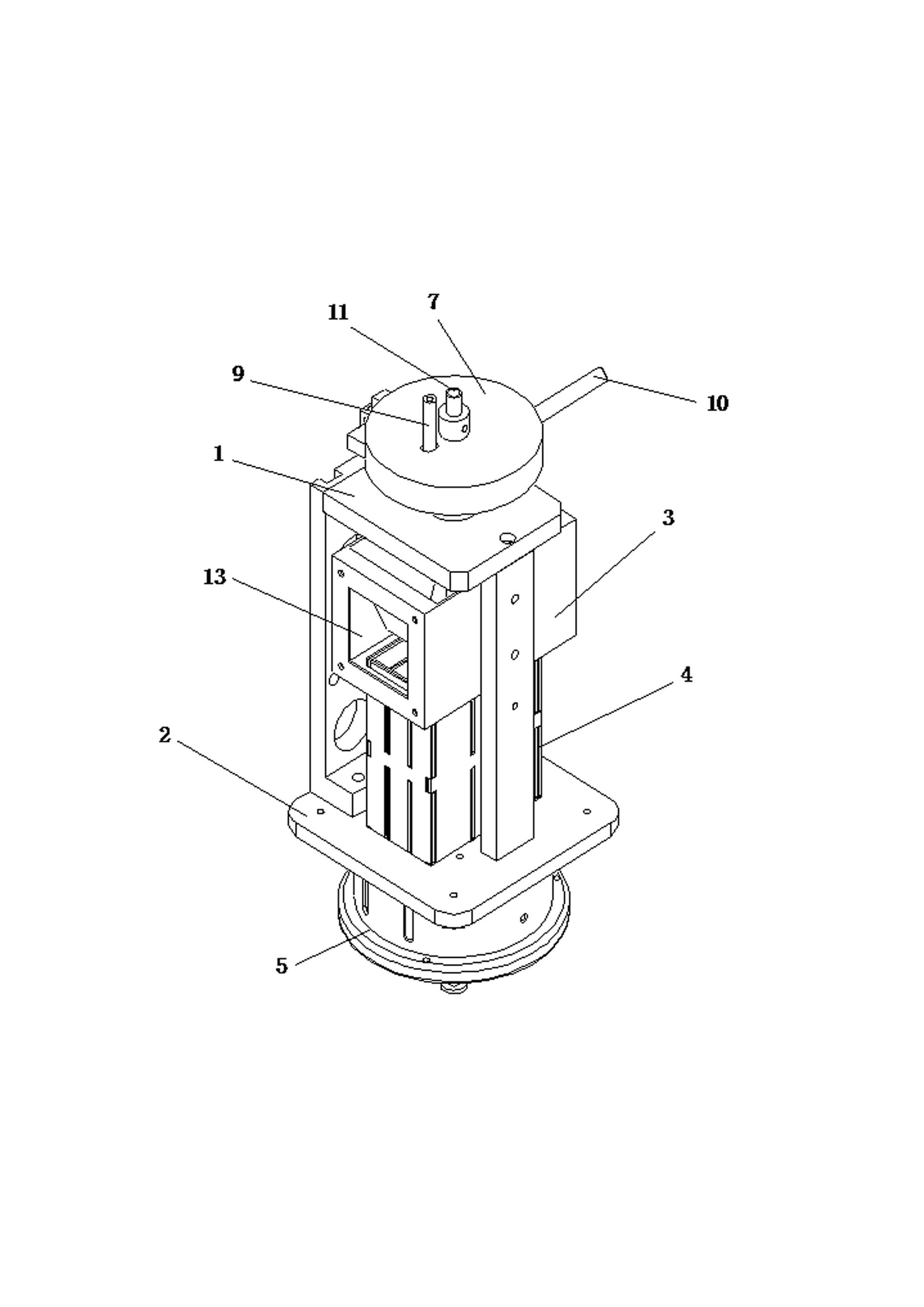
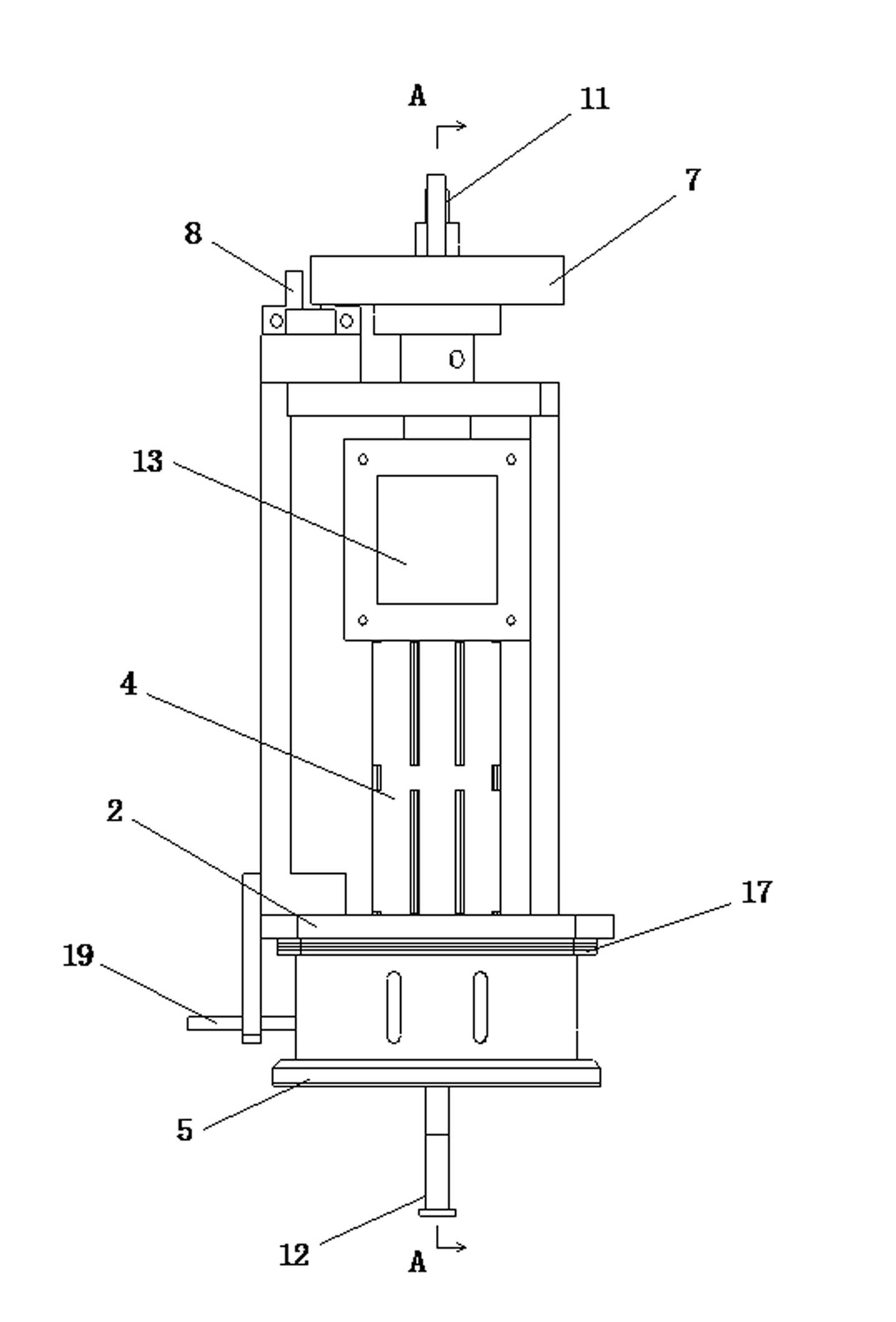
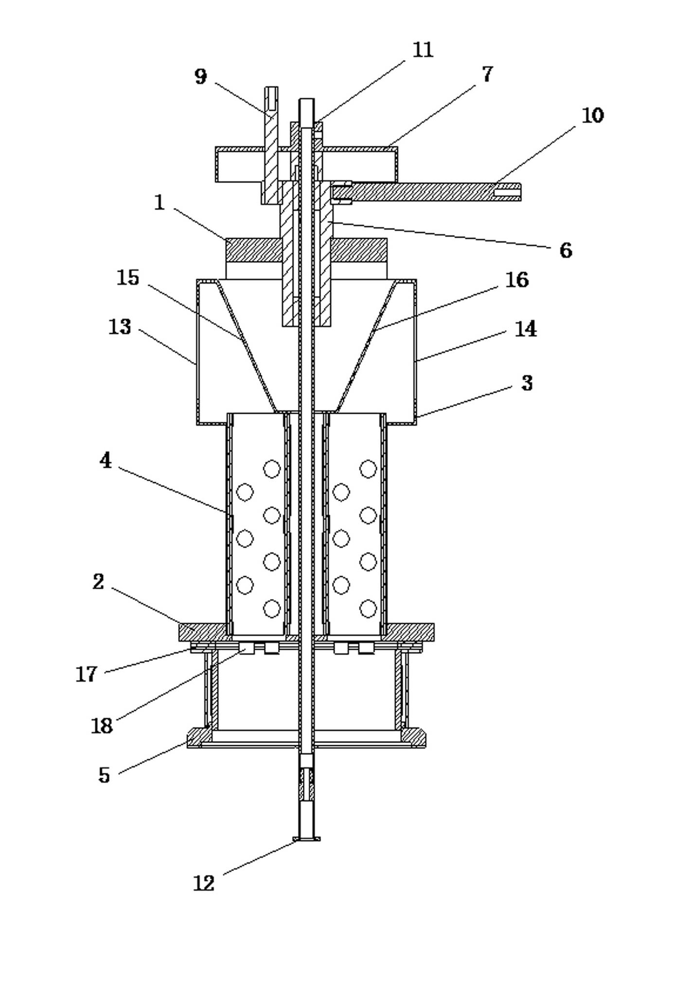
[0023] like Figure 1 to Figure 4 As shown, a heating and mounting integrated hot air head is characterized in that a heating core fixing seat 3 and a heating wire support 4 are installed between the upper and lower fixing plates 1 and 2, and the bottom of the lower fixing plate 2 is installed with The nozzle seat 5 and the upper fixing plate 1 are pierced with a hollow suction rod guide sleeve 6. The lower end of the suction rod guide sleeve 6 extends into the heating core fixing seat 3. The upper part of the suction rod guide sleeve 6 is equipped with a rotating induction coil 7. A sensor 8 is also arranged near the rotation induction coil 7, and a rotation transmission rod 9 is arranged between the rotation induction coil 7 and the suction rod guide sleeve 6, and the suction rod guide sleeve 6 is also connected with a rotation rod 10, and a suction rod 11 is induced by rotation. After the ring 7 enters, it passes through the suction rod guide sleeve 6 and extends out of the...


PUM


Abstract

The invention discloses an integrated heating-placement hot air head which is characterized in that a heater fixing seat and a heater support are arranged between an upper fixing plate and a lower fixing plate; a nozzle holder is arranged at the bottom of the lower fixing plate; a hollow sucking rod guiding sleeve is arranged in the upper fixing plate in a penetrating way; the lower end of the sucking rod guiding sleeve extends into the heater fixing seat; a rotating induction coil is arranged at the upper part of the sucking rod guiding sleeve; a sensor is also arranged beside the rotating induction coil; a rotating driving rod is arranged between the rotating induction coil and the sucking rod guiding sleeve; the sucking rod guiding sleeve is connected with a rotating rod; a sucking rod enters from the rotating induction coil, penetrates the sucking rod guiding sleeve and extends out of the nozzle holder; and a suction nozzle is also arranged at one end of the sucking rod outside the nozzle holder. The hot air head disclosed by the invention has the advantages of simple and reasonable structure, small volume, low cost, uniform heating temperature, rapid heating and cooling, long service life, excellent heat resistance, low heat loss, capability of ensuring placement accuracy and reliability, and convenient installation and maintenance.

Description

technical field [0001] The invention relates to the technical field of printed circuit board welding machines, in particular to a heating and mounting integrated hot air head. Background technique [0002] The existing printed circuit board welding machine still has the following disadvantages in its hot air head: (1) Since the heating and mounting mechanism are not integrated (independently), the product is large in size and needs to occupy a certain space, and its manufacturing cost High, and affect work efficiency; (2) The temperature of the heating wire in the hot air head is uneven, the heating / cooling is slow, and the life of the heating wire is not good; (3) The existing hot air head, the hot air cannot directly act on the chip , the heat loss is large, and it is difficult to achieve infrared heating; (4) Affected by the traditional vacuum connection method, the micro-movement of the suction rod is easily affected by the vacuum connection tube, and it is difficult to ...

Claims


Application Information

Patent Timeline
IPC IPC(8): B23K3/053
Inventor 杨凯洪军
Owner SHENZHEN JT AUTOMATION EQUIP CO LTD
Why Eureka
Try Eureka