
Piezoelectric diaphragm and piezoelectric electroacoustic converter using piezoelectric diaphragm

A piezoelectric and diaphragm technology, applied in piezoelectric/electrostrictive transducers, piezoelectric effect/electrostrictive or magnetostrictive motors, piezoelectric devices/electrostrictive devices, etc. Problems such as reduction of mechanical strength of ceramic body 41

Inactive Publication Date: 2007-12-19
MURATA MFG CO LTD
View PDF4 Cites 4 Cited by
  • Summary
  • Abstract
  • Description
  • Claims
  • Application Information

AI Technical Summary

Problems solved by technology

Another cause of cracks is that the provision of the cutouts 45a, 46a, 45b and 46b results in a decrease in the mechanical strength of the multilayer ceramic body 41.

Method used


Image

  • Piezoelectric diaphragm and piezoelectric electroacoustic converter using piezoelectric diaphragm
  • Piezoelectric diaphragm and piezoelectric electroacoustic converter using piezoelectric diaphragm
  • Piezoelectric diaphragm and piezoelectric electroacoustic converter using piezoelectric diaphragm

Examples


Embodiment Construction

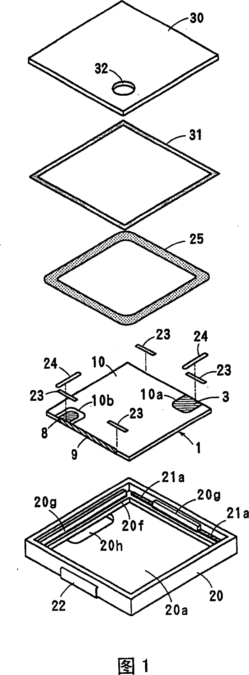
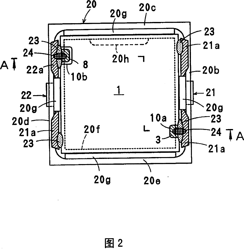
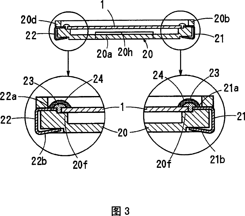
[0029] 1 to 3 show a surface mount type piezoelectric electroacoustic transducer in a first preferred embodiment according to the present invention.

[0030] The electro-acoustic transducer according to this preferred embodiment is suitable for applications such as piezoelectric receivers, where the electro-acoustic transducer needs to work in a wide frequency range. The electroacoustic transducer includes a piezoelectric diaphragm 1 , a case 20 , and a cover 30 . The box 20 and the cover 30 define a housing.

[0031] As shown in FIGS. 4 to 6 , the piezoelectric diaphragm 1 includes an almost rectangular multilayer ceramic body 2 preferably formed by laminating two piezoelectric ceramic layers 2 a and 2 b , although more layers may also be used. Main surface electrodes 3 , 4 are arranged on the upper and lower main surfaces of the multilayer ceramic body 2 . Internal electrodes 5 and dummy electrodes 6 are arranged between ceramic layers 2a and 2b. The two ceramic layers 2a...


PUM

PropertyMeasurementUnit
sizeaaaaaaaaaa
tensile modulusaaaaaaaaaa

Abstract

A piezoelectric diaphragm has principal-surface electrodes formed on upper and lower principal surfaces of a multilayer ceramic body. An internal electrode is disposed in an interface between adjacent piezoelectric ceramic layers. The upper and lower principal surfaces of the multilayer ceramic body are substantially entirely covered with a resin layer. A first cutout is formed in a side-edge portion, along the first side surface electrode, of the upper resin layer such that the upper principal-surface electrode is partially exposed in the first cutout. A second cutout is formed in a side-edge portion, along the first side surface electrode, of the lower resin layer such that the lower principal-surface electrode is partially exposed in the second cutout. The locations of the first and second cutouts formed in the upper and lower resin layers, respectively, are selected such that they do not oppose each other.

Description

technical field [0001] The present invention relates to piezoelectric diaphragms for use in piezoelectric receivers, piezoelectric acoustics or other suitable devices, and also to piezoelectric electroacoustic transducers comprising such piezoelectric diaphragms. Background technique [0002] Piezoelectric electroacoustic transducers are widely used in piezoelectric speakers, piezoelectric receivers, or other components in other piezoelectric devices, household appliances, mobile phones or devices. In such a piezoelectric electroacoustic transducer, Japanese Unexamined Patent Application Publication No. 2001-95094 proposes to use a bimorph element piezoelectric diaphragm made of a multilayer piezoelectric ceramic. [0003] The piezoelectric diaphragm disclosed in Japanese Unexamined Patent Application Publication No. 2001-95094 is a multilayer ceramic body manufactured by laminating two or three piezoelectric ceramic layers. Major surface electrodes are disposed on the uppe...

Claims


Application Information

Patent Timeline
Patent Type & Authority Patents(China)
IPC IPC(8): H04R17/00H01L41/083H01L41/09H02N2/04
CPCH01L41/0973H04R17/00H01L41/0926H01L41/083H10N30/50H10N30/2047
Inventor 竹岛哲夫田岛清高小杉裕二
Owner MURATA MFG CO LTD
Learn More