Component belt conveyor wheel, component belt conveyor system and method for operating a component belt conveyor system

A technology of conveying system and component belt, applied in the direction of electrical components, electrical components, etc., can solve the problem of unable to pick up position correction, etc., and achieve the effect of high positioning accuracy and high precision

Inactive Publication Date: 2008-01-09
SIEMENS ELECTRONICS ASSEMBLY SYST LLC
View PDF3 Cites 2 Cited by
  • Summary
  • Abstract
  • Description
  • Claims
  • Application Information

AI Technical Summary

Problems solved by technology

[0006] However, input modules with mechanically predetermined step lengths for stationary have the disadvantage that on the one hand only a single step length of the tape can be used and on the other hand no correction of the pick-up position is possible since the tape is always transported onwards a specified length

Method used


Image

  • Component belt conveyor wheel, component belt conveyor system and method for operating a component belt conveyor system
  • Component belt conveyor wheel, component belt conveyor system and method for operating a component belt conveyor system

Examples


Embodiment Construction

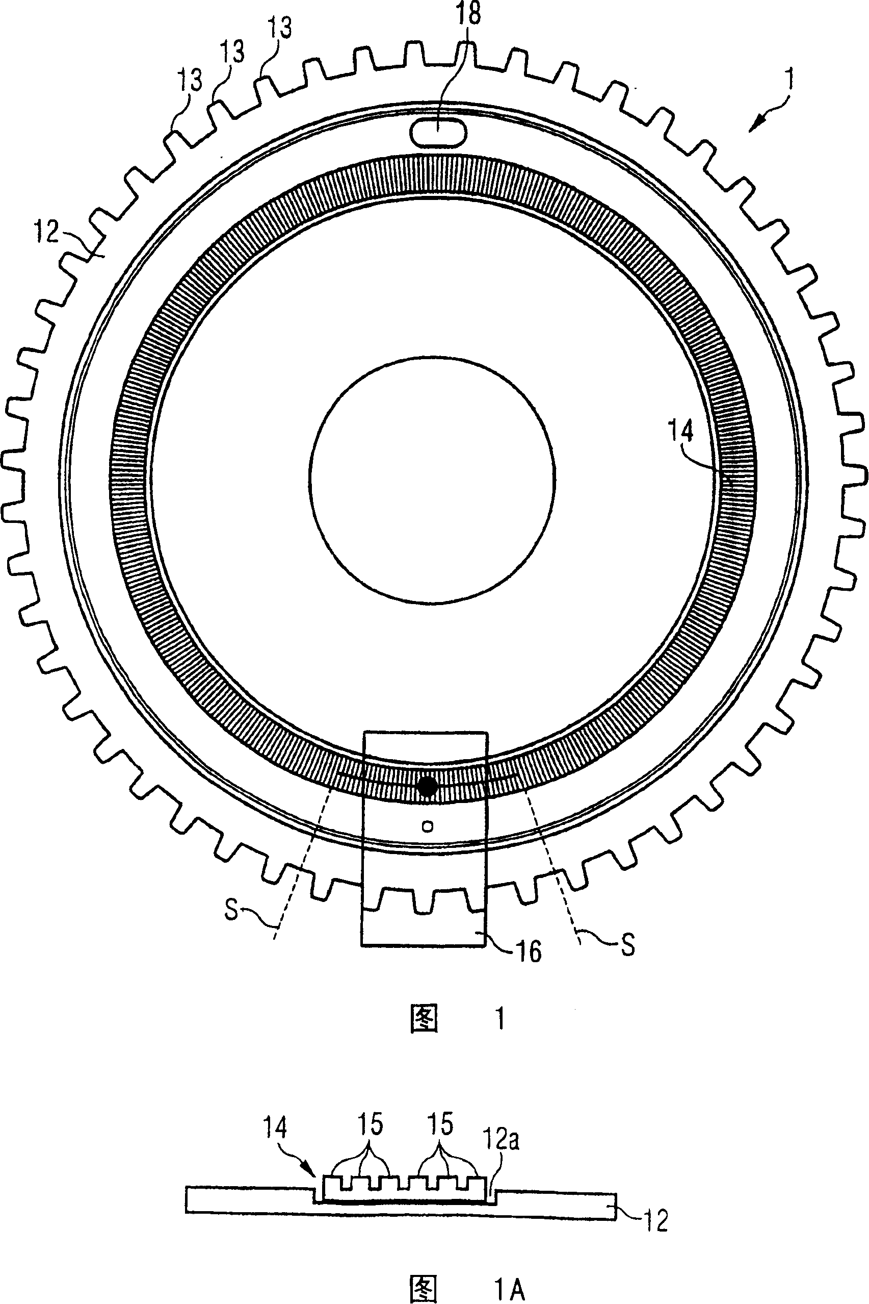
[0030] It can be seen from FIG. 1 that a schematic top view of a component belt conveyor wheel according to the invention is shown. The conveyor wheel 1 has an essentially disk-shaped body 12 provided with a plurality of conveyor pins 13 which are each arranged radially. The transport pins 13 are suitable to engage in their transport openings during the transport of the component strips in order to enable the transport of the component strips which is brought about by the rotation of the transport wheels.

[0031] An encoder wheel 14 is mounted on the disk-shaped body 12, for example in an annular groove. The encoder wheel 14 is firmly coupled to the disc-shaped object 12, so that a one-to-one correspondence between the conveying pins 13 and the encoder elements of the encoder wheel 14 is possible. If the component belt conveyor wheel 1 according to the invention passes by a sensor 16, which can detect the encoder element of the encoder wheel, then in cooperation with this se...


PUM


Abstract

A component tape transport wheel, a component tape transport system and a method of operating a component tape transport system are provided, in which there is a rigid coupling between a transport wheel and an encoder wheel which is arranged on the transport wheel and whose position relative to a sensor can be determined. By this rigid coupling between the transport wheel which moves the component tape and a registration system including an encoder wheel and sensor for registering the position of the transport wheel, it is possible to register the position of the transport wheel at any time with the greatest accuracy. Even after a component tape transport system has been switched off, a determination of the absolute position of the transport wheel is possible, since the distance between two encoder elements of the encoder wheel is less than any play possibly caused by a drive of at least one of the transport wheel and an associated gear mechanism.

Description

technical field [0001] The invention relates to a component tape conveyor wheel, a component tape conveyor system and a method of operation of the component tape conveyor system, in which the component tape conveyor wheel has a disk-shaped inner shell on which a plurality of conveyor pins are respectively Arranged radially, these pins can engage in their transport holes when transporting the component strip. Background technique [0002] Component tape is currently the most important form of packaging for components. Strips of components are suitable for both high-volume and small-batch production, and they often require retooling. The component tape can be used to assemble, for example, SMD (Surface Mount Device) components by means of an input module of an assembly device. The task of the input module is to ensure that the element consisting of strips is available without interference. The component tape is moved from a roller into the input module, wherein the cover ta...

Claims


Application Information

Patent Timeline
Patent Type & Authority Patents(China)
IPC IPC(8): H05K13/02
CPCH05K13/021H05K13/0419H05K13/02
Inventor T·利贝克H·瓦尔纳
Owner SIEMENS ELECTRONICS ASSEMBLY SYST LLC
Why Eureka
Try Eureka