
Method for flow improvement and reduction of fouling in process equipment

A process equipment and fouling technology, applied in chemical instruments and methods, pollution prevention methods, heat transfer modification, etc., can solve the problem of reducing the scaling rate and achieve the effect of reducing the deposition rate

Inactive Publication Date: 2008-01-16
EMT RES AS
View PDF5 Cites 0 Cited by
  • Summary
  • Abstract
  • Description
  • Claims
  • Application Information

AI Technical Summary

Problems solved by technology

[0008] However, theoretical and experimental studies have been carried out to understand the fouling mechanism in heat exchangers and to reduce the fouling rate

Method used


Image

  • Method for flow improvement and reduction of fouling in process equipment
  • Method for flow improvement and reduction of fouling in process equipment
  • Method for flow improvement and reduction of fouling in process equipment

Examples


Embodiment Construction

[0027] The present invention will now be described in more detail with reference to preferred embodiments of the invention.

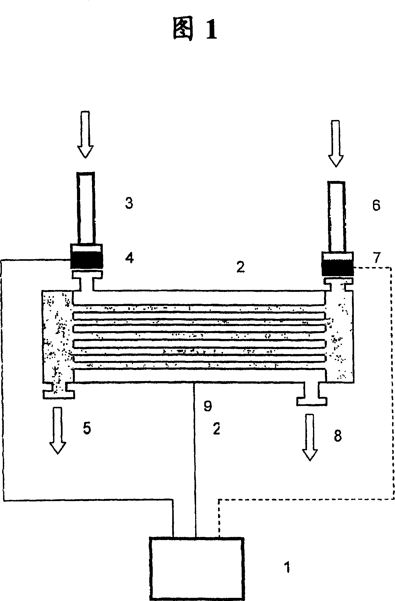
[0028] A preferred embodiment of the invention as implemented on a shell and tube heat exchanger is schematically shown in FIG. 1 . Arrows indicate flow direction. The invention 1 can be connected to the heat exchanger 2 by conventional two or more connectors (not shown in the figure). A connector is attached to the ring 4 in the inlet for the cooling / heating medium 3, which is electrically insulated from the rest of the system. A connector is connected to the ring 7 in the inlet for the process fluid 6, which is also electrically isolated from the rest of the system. The third connector is connected at point 9 on the heat exchanger itself. If the invention is used to improve the flow of a process fluid, the connection point 9 will be at the outlet of the process fluid 5 . In order to improve the flow of the cooling / heating medium, a connection poin...


PUM

PropertyMeasurementUnit
sizeaaaaaaaaaa
sizeaaaaaaaaaa

Abstract

This invention relates to a method and apparatus for improvement of flow rates and reduction of fouling in process equipment such as for instance heat exchangers (2) where fluids are flowing in single or multiphase. This is obtained by imposing a DC-potential at the walls of the process equipment that exactly opposes the naturally ocurring potential due to interaction between the walls of the process equipment and the fluid flowing inside. An improved flow rate will cause that the heat exchanger (2) becomes more efficient, i.e. a lower deposition rate and a higher removal rate of inorganic agents. The fluid may be a pure fluid, colloidal fluid or contain inclusions in the form of particles.

Description

technical field [0001] The present invention relates to methods and apparatus for increasing flow rates and reducing fouling in process equipment such as heat exchangers in which fluids flow in single or multiple phases. An increased flow rate will result in a more efficient heat exchanger, ie a lower deposition rate and a higher removal rate of inorganic reagents. Fluids may be pure fluids, colloidal fluids, or contain inclusions in particulate form. Background technique [0002] The formation of deposits (fouling) on ​​heat transfer surfaces is a major cost factor in the installation and operation of heat exchangers. Accumulation of deposits on heat transfer surfaces often results in reduced heat transfer rates and can cause other operational problems. Heat exchangers are used in almost all industries, including process and petroleum industries. Consequently, fouling problems exist in almost all industries. The total fouling-related costs to the industry are estimated ...

Claims


Application Information

Patent Timeline
Patent Type & Authority Patents(China)
IPC IPC(8): C02F1/48B08B17/00C02F1/00F28F13/16F28F19/00
CPCF28F13/16C02F2209/06B08B17/00C02F2209/03C02F2209/40C02F1/4602C02F2209/05F28F19/004C02F2303/22C02F1/008
Inventor M·瓦斯卡斯
Owner EMT RES AS
Learn More