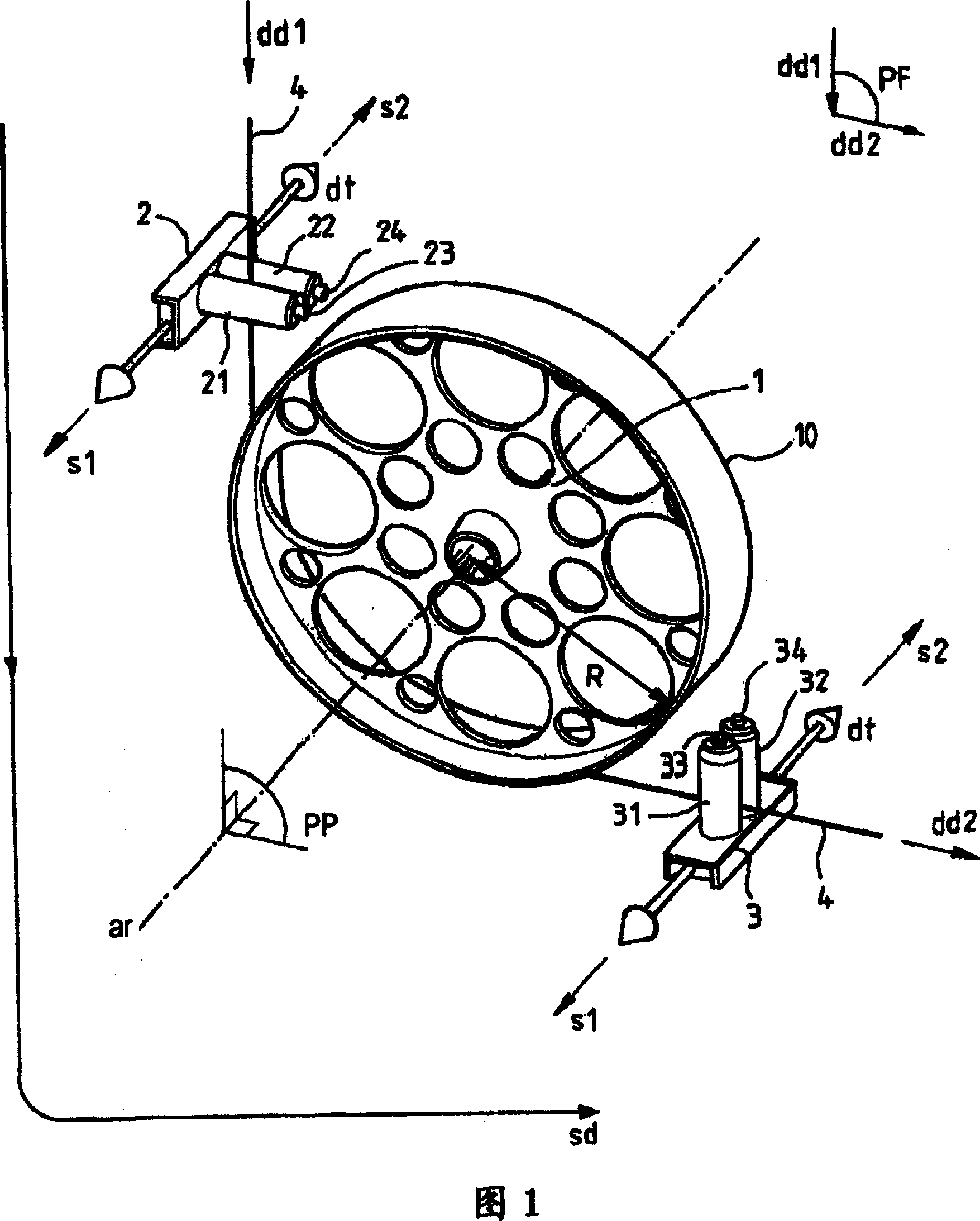
Anti-PMD system

A technology of pulleys and optical fibers, applied in the field of anti-PMD systems, can solve problems such as constant deviation, reduction of twisting torque of anti-PMD pulleys, and reduced effectiveness

Inactive Publication Date: 2008-02-06
ALCATEL LUCENT SAS
View PDF7 Cites 0 Cited by
  • Summary
  • Abstract
  • Description
  • Claims
  • Application Information

AI Technical Summary

Problems solved by technology

This third prior art provides sufficient control over the rotation of the optical fiber at moderate fiber pulling speeds, but at the expense of additional disadvantages
These additional disadvantages include a mechanical system that is complex and fragile for wedging the optical fiber when trying not to damage it excessively, and at high fiber drawing speeds, typically 1000 meters per minute ( m / min) above, these problems are about the quality of the coating if the optical fiber is too tightly wedged between the anti-PMD pulleys, or about if the optical fiber is not wedged tightly enough between the anti-PMD pulleys Guidance problem of indirect view optical fiber
The guiding problem results in a reduction in the contact duration between the optical fiber and the anti-PMD pulley, and thus reduces the effectiveness of the rotation of the optical fiber on the anti-PMD pulley, thereby reducing the twisting rotation that the anti-PMD pulley applies to the optical fiber. moment, and thus in the final optical fiber, i.e. in the fiber at the end of the drawn fiber, resulting in too large a PMD value
This type of system, which compresses the optical fiber between two anti-PMD pulleys, handles very poorly the problems associated with changes in the diameter of the optical fiber, because whenever the diameter of the optical fiber changes, the pressure is either too high or too small

Method used


Image

  • Anti-PMD system

Examples


Embodiment Construction

[0010] The various steps of making the optical fiber during the fiber drawing process have a major effect on the ovalization of the refractive index and shape of the preform core, and thus also of the optical fiber, where such ovalization constitutes One of the causes of considerable PMD. Optical fibers in which the PMD is too large cannot be sold because the PMD attenuates the optical signal carried by the optical fiber to an excessive extent. A method for reducing the PMD of an optical fiber during fiber drawing consists in twisting the optical fiber about its own axis alternately in one direction of rotation, eg clockwise, and then in another direction, eg counterclockwise. The anti-PMD system for twisted optical fibers is located at the bottom of the fiber-drawing tower and preferably acts on the optical fiber when it has been covered with two covering layers. The twisting torque applied to the optical fiber is transmitted all the way to the viscous cone of the preform gl...


PUM


Abstract

The invention provides an anti-PMD system comprising: an anti-PMD pulley (1) over which an optical fiber (4) is to roll and which is mounted to rotate about an axis of rotation (ar); and at least two optical fiber guide devices (2, 3) situated on either side of the anti-PMD pulley (1); the axis of rotation (ar) of the anti-PMD pulley (1) being stationary; the only degree of freedom of the anti-PMD pulley (1) being rotation about the axis of rotation (ar) of the anti-PMD pulley (1); and at least one of the guide devices (2, 3) being movable in translation in a translation direction (dt) that is not orthogonal to the axis of rotation (ar) of the anti-PMD pulley (1).

Description

technical field [0001] The present invention relates to the field of anti-PMD systems for reducing the PMD of optical fibers during the fiber drawing process. PMD stands for Polarization Mode Dispersion. Polarization mode dispersion is a disadvantage of optical fibers because it leads to attenuation of signal propagation in the optical fiber. This shortcoming becomes more and more serious with the application of increasing data rates in fiber optic communication networks. Background technique [0002] In a first prior art, it is known to use an anti-PMD system called "SZ system". This system is based on the use of an oscillating rotating pulley. The oscillating pulley is an anti-PMD pulley. Such a system is described, for example, in European patent EP 0 582 405 incorporated herein by reference, or in European patent EP 0 744 636 . The SZ system is located at the bottom of the fiber draw tower, in the plane defined around the bend of the optical fiber through the anti-P...

Claims


Application Information

Patent Timeline
IPC IPC(8): C03B37/02G02B6/00C03B37/12C03B37/03
CPCC03B2205/06C03B37/032C03B2203/19C03B2203/36
Inventor 卡梅尔·杜格达格埃里克·兰特
Owner ALCATEL LUCENT SAS
Why Eureka
Try Eureka