Supercharge Your Innovation With Domain-Expert AI Agents!

Wet type dust collection unit

A dust collection device, wet technology, applied in the direction of combination device, disperse particle filtration, use of liquid separation agent, etc., can solve the problem of increasing the load of the septic tank, and achieve the effect of reducing the load of the septic tank and reducing the load

Inactive Publication Date: 2008-03-05
SHIN MEIWA IND CO LTD
View PDF3 Cites 0 Cited by
  • Summary
  • Abstract
  • Description
  • Claims
  • Application Information

AI Technical Summary

Problems solved by technology

However, if a new septic tank is installed, the overall size of the system including both the wet dust collector and the septic tank cannot be avoided.
In addition, even when using an existing septic tank, there is a problem that the load on the septic tank increases

Method used


Image

  • Wet type dust collection unit
  • Wet type dust collection unit
  • Wet type dust collection unit

Examples


Embodiment 1

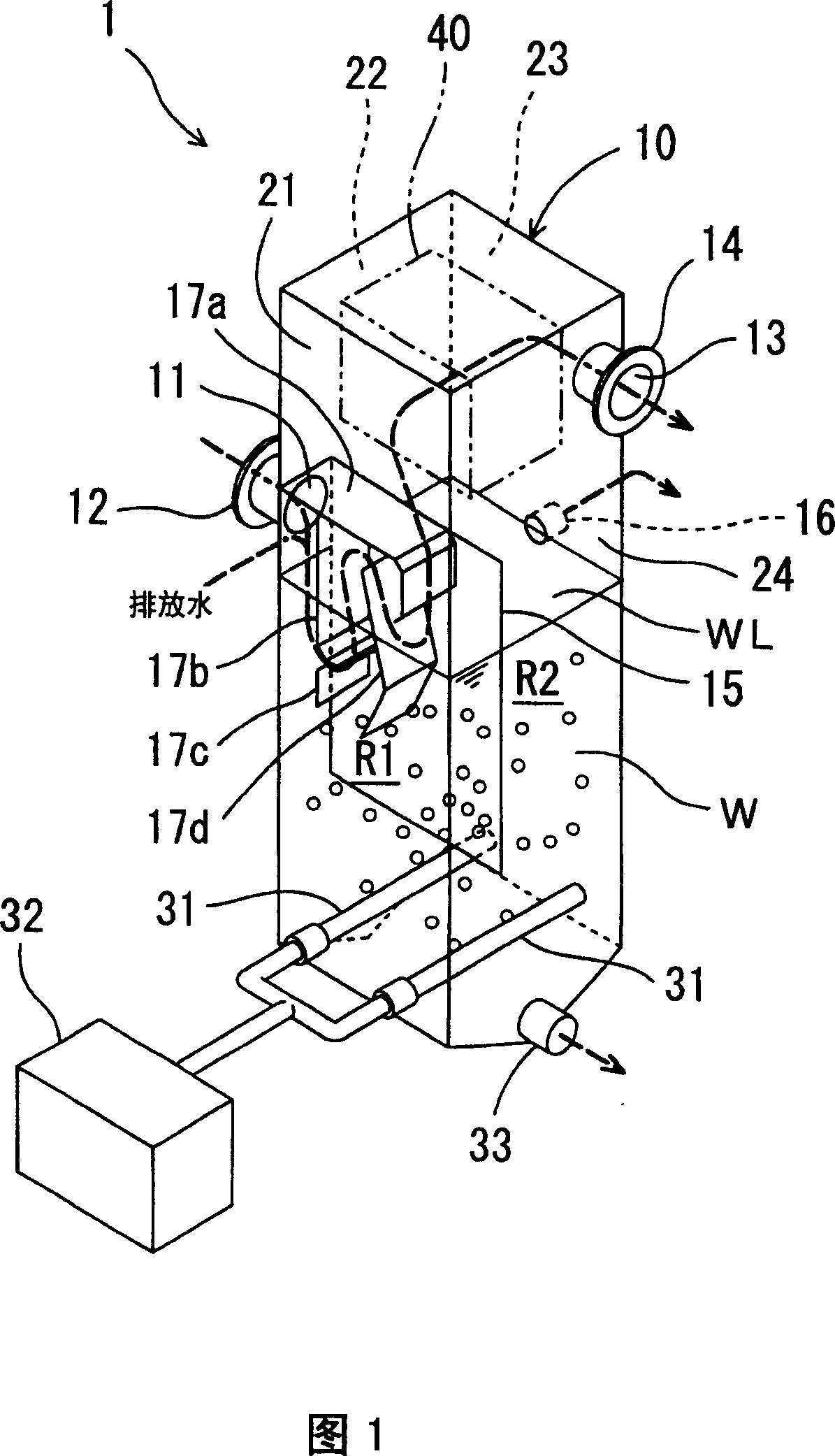
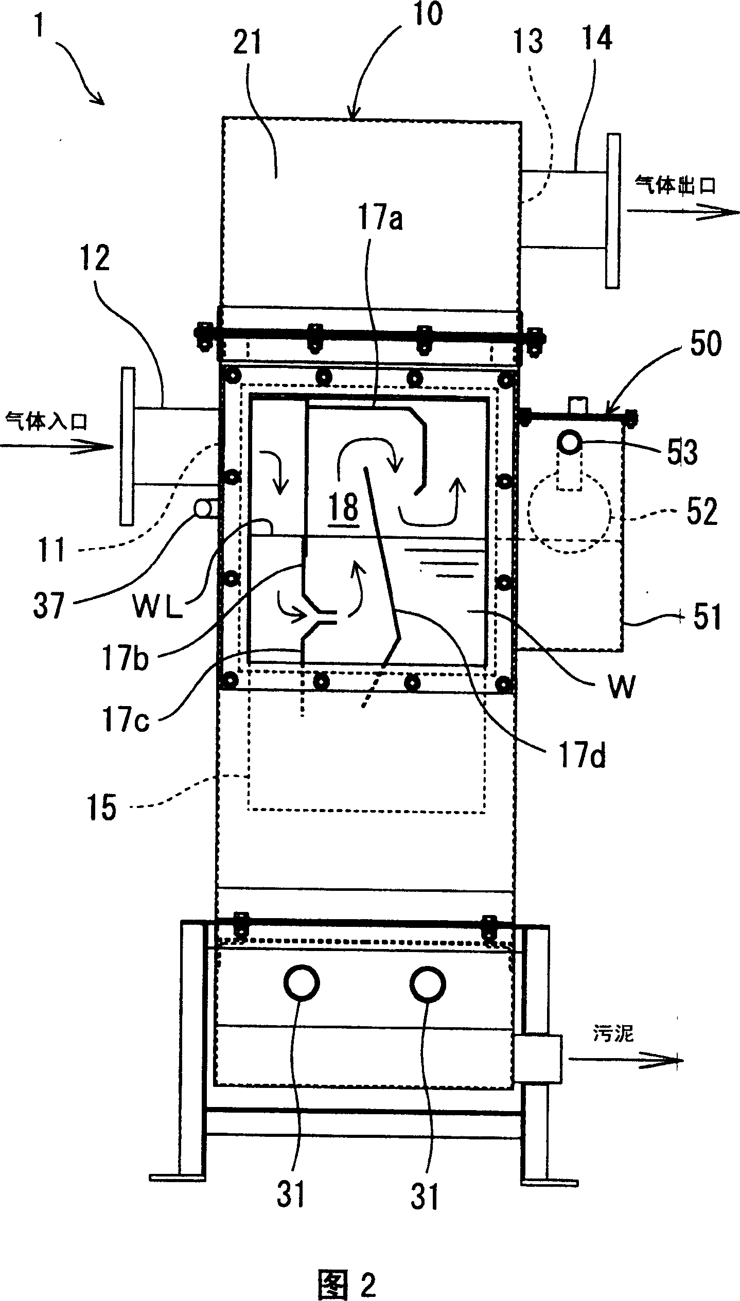
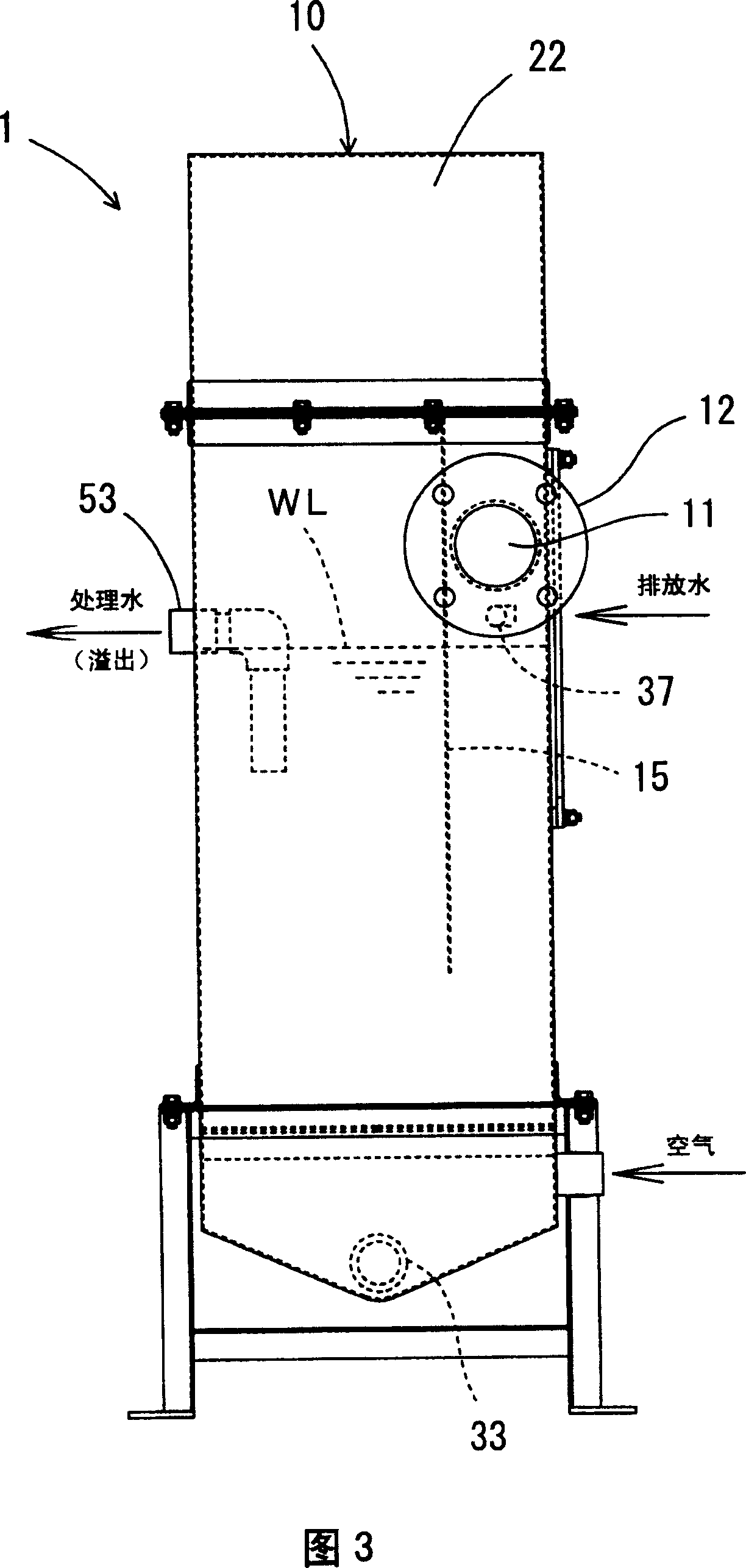
[0032] As shown in FIGS. 1 to 4 , the wet dust collector 1 includes a vertically long substantially rectangular parallelepiped airtight casing 10 . On the left side 22 of the casing 10, an air inlet 11 for introducing gas is formed. The air intake port 11 is located on the upper side slightly higher than the vertically central portion of the left side surface 22 and is formed on the front end side. A suction pipe 12 is provided around the suction port 11 . On the right side 24 of the casing 10, an exhaust port 13 for leading out gas is formed. The exhaust port 13 is formed on the upper end side and the rear end side of the right side surface 24 . An exhaust pipe 14 is provided around the exhaust port 13 .

[0033] Treated water W is stored inside the housing 10 . To the rear side 23 of the casing 10, an overflow pipe 16 for discharging the treated water W whose water volume has been increased is connected. Therefore, the height of the liquid level WL of the treated water ...


PUM


Abstract

To provide a wet dust collector alleviating the load of the purifying tank in purifying the treatment solution after dust collection of exhaust gas or eliminating the need of the tank. In a casing 10, a division plate 15 dividing the first space R1 and the second space R2 and the first to fourth passage-forming plates 17a to 17d forming gas passages in the first space R1 are provided. A deodorizing material 40 is arranged in the second space R2. A gas-supplying pipe 31 supplying air from a blower 32 to the treating water W is arranged in the bottom of the casing 10. The treatment water W contains aerobic microorganisms. The treatment water W is treated by aeration with the air from the gas-supplying pipe 31.

Description

technical field [0001] The invention relates to a wet dust collecting device. Background technique [0002] Conventionally, wet dust collectors have been used for the purpose of dust collection such as high-temperature or low-temperature exhaust gas or exhaust gas containing ignition materials (see, for example, Patent Document 1 below). A wet dust collector is a device that removes dust from a gas containing dust by bringing the gas into contact with a liquid. [0003] Generally, a wet dust collector is provided with a closed casing, and a flow path through which gas containing dust flows is formed inside the casing. The flow path is formed to zigzag up and down, and the lower side of the flow path is immersed in a dust collecting liquid (hereinafter referred to as treatment liquid). [0004] The gas introduced into the casing comes into contact with the processing liquid while passing through the flow path. At this time, dust contained in the gas is removed by the treat...

Claims


Application Information

Patent Timeline
Patent Type & Authority Patents(China)
IPC IPC(8): B01D47/02
CPCY02W10/10B01D47/021B01D53/38B01D53/78B01D53/84B01D46/0028B01D46/0038B01D2251/104B01D50/60
Inventor 须贺雅庸岩上修治加藤淳志
Owner SHIN MEIWA IND CO LTD
Features
  • R&D
  • Intellectual Property
  • Life Sciences
  • Materials
  • Tech Scout
  • Unparalleled Data Quality
  • Higher Quality Content
  • 60% Fewer Hallucinations
Learn More