Dynamic regulating circuit and method of basic time pulse signal for front and bus bar

A technology of dynamic adjustment and busbar, applied in the direction of generating/distributing signals, etc., can solve the problems of poor adjustment efficiency, inability to effectively save power, and collocation use

Active Publication Date: 2008-03-26
VIA TECH INC
View PDF6 Cites 0 Cited by
  • Summary
  • Abstract
  • Description
  • Claims
  • Application Information

AI Technical Summary

Problems solved by technology

However, this method of driving the embedded controller 40 through the system management bus 45 to adjust by software is quite complicated, so the adjustment efficiency is poor. In addition, the adjustment method through the system management bus 45 cannot match the operating system of the computer. In this way, it cannot be used in conjunction with a software program that is installed in the operating system and can detect the workload of the central processing unit 20, that is, the existing known adjustment method cannot automatically adjust the front-end confluence according to the workload of the central processing unit 20. The basic clock signal of row 33, so the purpose of saving power cannot be effectively achieved
[0009] Therefore, the present invention proposes a dynamic adjustment circuit and method for the basic clock signal of the front-end bus to solve the above problems, which can not only improve the disadvantages of complicated adjustments in the prior art, but also be compatible with software programs installed in the operating system. Used to automatically adjust the frequency of the basic clock signal of the front-end bus according to the workload of the central processing unit, so as to improve the efficiency of power saving
[0010] It can be seen that the above-mentioned existing method for adjusting the basic clock signal obviously still has inconvenience and defects in terms of structure, method and use, and needs to be further improved urgently.
In order to solve the problems existing in the way of adjusting the basic clock signal, the relevant manufacturers have tried their best to find a solution, but no suitable design has been developed for a long time, and there is no suitable design for general products and methods. To solve the above problems, this is obviously a problem that the relevant industry is eager to solve

Method used


Image

  • Dynamic regulating circuit and method of basic time pulse signal for front and bus bar
  • Dynamic regulating circuit and method of basic time pulse signal for front and bus bar
  • Dynamic regulating circuit and method of basic time pulse signal for front and bus bar

Examples


Embodiment Construction

[0061] In order to further explain the technical means and effects of the present invention to achieve the intended invention purpose, the circuit and method for dynamically adjusting the basic clock signal of the front-end busbar according to the present invention will be described below in conjunction with the accompanying drawings and preferred embodiments. Its specific implementation, structure, adjustment method, steps, features and effects thereof are described in detail below.

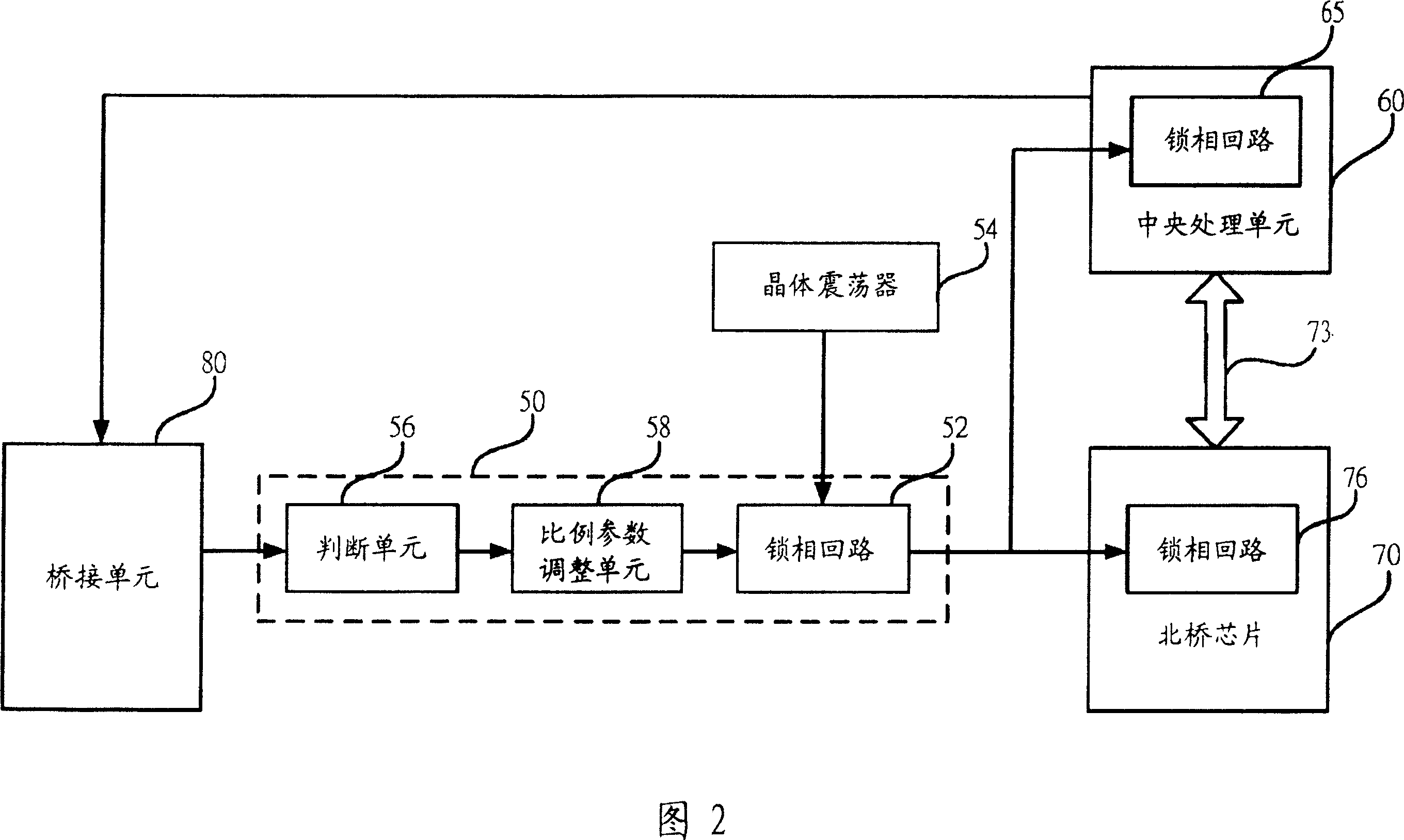
[0062] Please refer to FIG. 2 , which is a block diagram of a preferred embodiment of the present invention. As shown in the figure, the phase-locked loop 52 of the clock generator 50 receives the fixed clock signal generated by the crystal oscillator 54 and generates a basic clock signal according to the proportional factor (M / N) shown in the first formula (1). , to generate the working clock signal of the central processing unit 60 with the phase-locked loop 65 transmitted to the central proce...


PUM


Abstract

In time of CPU operation, the invention adjusts a phase lock loop of computer in use for generating a scale factor value of basic time pulse signal for bus in front end in order to adjust frequency of basic time pulse signal. Based on a received selection signal from a bridge connection unit, the method outputs an adjusting signal to a corresponding judgment unit, which determines the adjusting signal and outputs a judgment signal to an adjustment unit for the scale factor. Based on the judgment signal, the adjustment unit for the scale factor adjusts value of first scale parameter in the scale factor used by current phase lock loop, and outputs the adjusted value to the phase lock loop. Thus, when generating basic time pulse signal after received a fixed time pulse signal, the phase lock loop generates basic time pulse signal of bus at front end based on adjusted value of first scale parameter so as to adjust frequency of basic time pulse signal.

Description

technical field [0001] The present invention relates to an adjustment circuit and method, in particular to a dynamic adjustment circuit and method for adjusting the basic clock signal of the front side bus (Front Side Bus), which can dynamically adjust the front side bus when the central processing unit is in operation The frequency of the basic clock signal. Background technique [0002] The invention of computer (that is, computer, hereinafter referred to as computer) can be said to be one of the most important scientific and technological inventions in the last century. It has greatly improved people's work efficiency. , pen writing, so quite time-consuming. In addition, in the past, after conceiving a new product concept, R&D personnel had to spend a considerable amount of time conducting complicated experiments to confirm whether it was feasible, which was quite tiring. Nowadays, due to the invention of computers, word processing personnel can quickly process paperwor...

Claims


Application Information

Patent Timeline
Patent Type & Authority Patents(China)
IPC IPC(8): G06F1/04
Inventor 郭宏益陈慧美
Owner VIA TECH INC
Why Eureka
Try Eureka