Supercharge Your Innovation With Domain-Expert AI Agents!

Strain tuning optical fiber grating dispersion dynamic compensation, monitoring device and method thereof

A technology of dynamic compensation and fiber grating, applied in the field of optical communication, can solve the problems of high price of bit error tester and difficult to be widely used, and achieve the effect of simple structure, reduced cost and simple components

Inactive Publication Date: 2008-04-02
SHANGHAI INST OF OPTICS & FINE MECHANICS CHINESE ACAD OF SCI
View PDF5 Cites 0 Cited by
  • Summary
  • Abstract
  • Description
  • Claims
  • Application Information

AI Technical Summary

Problems solved by technology

However, the bit error meter is expensive and difficult to be widely used

Method used


Image

  • Strain tuning optical fiber grating dispersion dynamic compensation, monitoring device and method thereof
  • Strain tuning optical fiber grating dispersion dynamic compensation, monitoring device and method thereof
  • Strain tuning optical fiber grating dispersion dynamic compensation, monitoring device and method thereof

Examples


Embodiment Construction

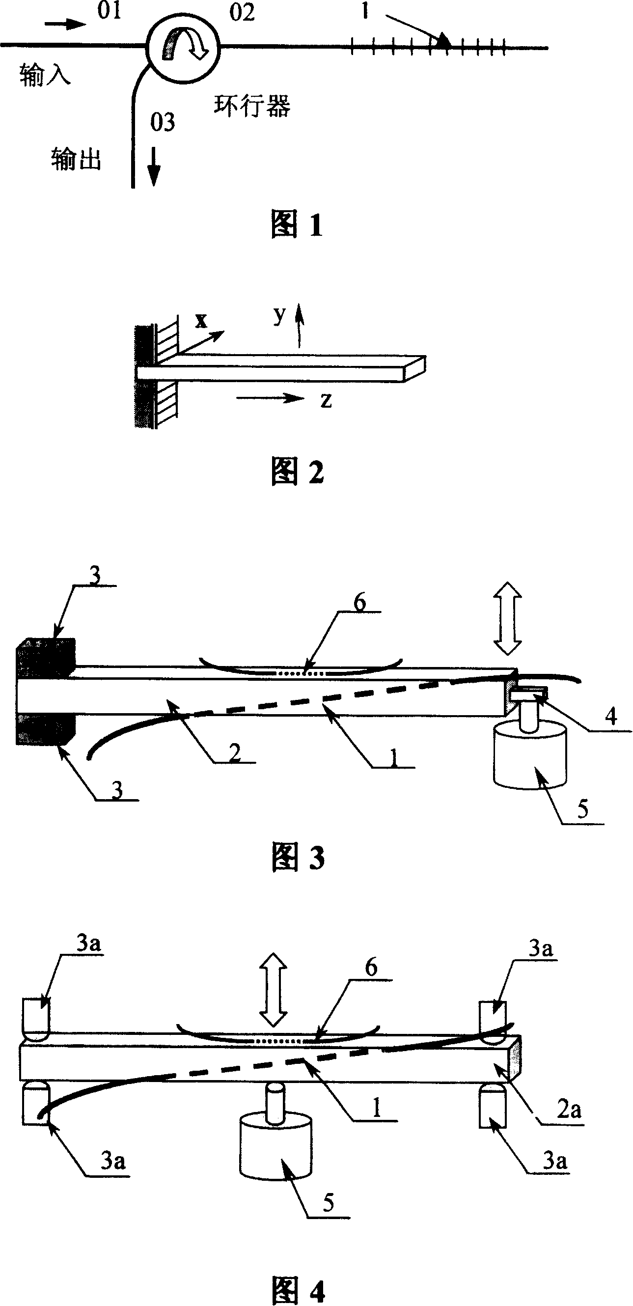
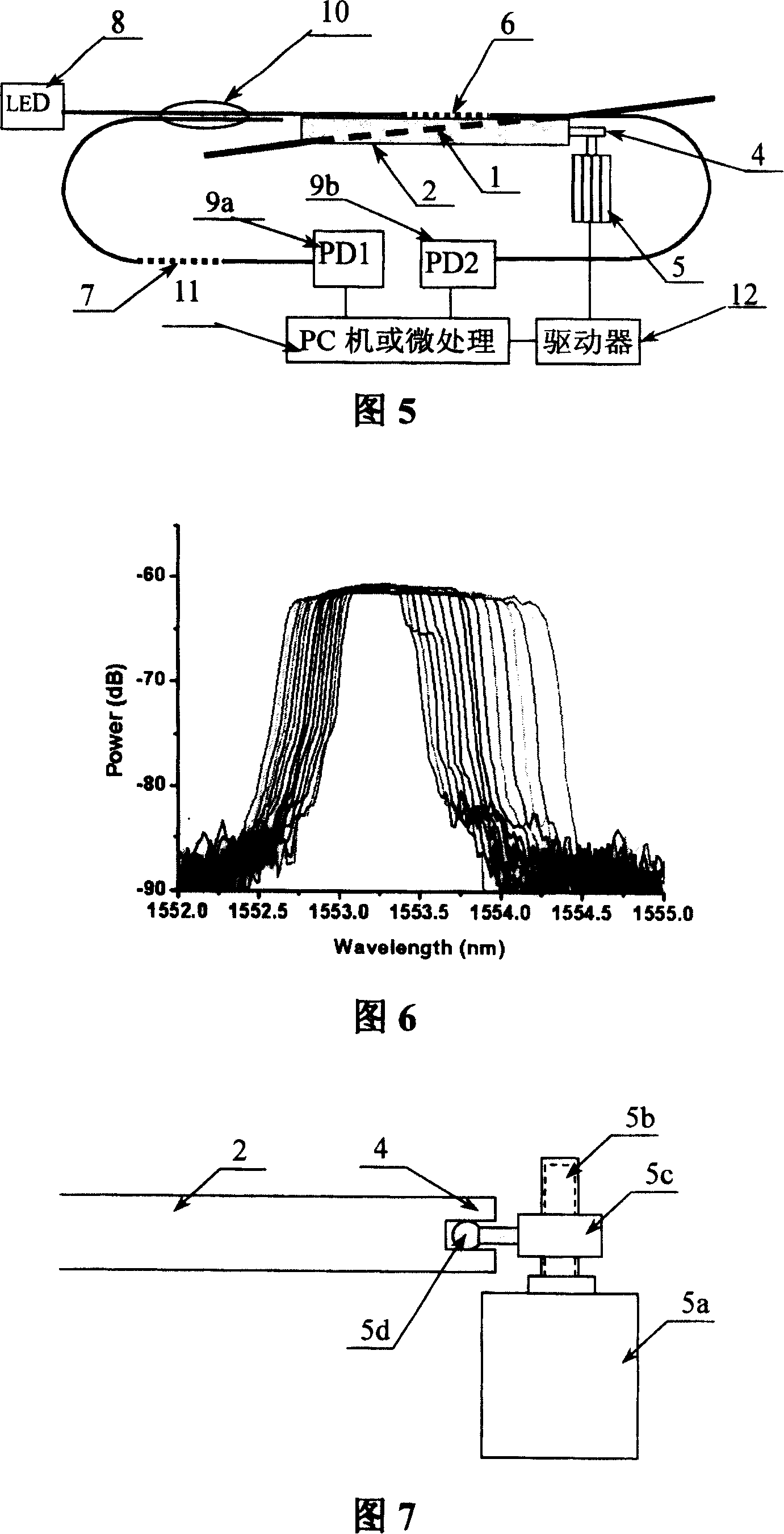
[0034] Please refer to FIG. 3 first. FIG. 3 is one of the partial structures of the device of the present invention, wherein 1 is a chirped fiber grating for dispersion compensation, and 2 is a cantilever beam used for tuning the chirped fiber grating 1 . The chirped fiber grating 1 is fixed on the side of the cantilever beam 2, 3 is the holder for installing the fixed end of the cantilever beam 2, 4 is the free end of the cantilever beam 2, and 5 is changing the strain state of the cantilever beam 2 by moving the free end 4 of the cantilever beam micro motor. 6 is a uniform (non-chirped) fiber grating fixed on the top surface of the cantilever beam 2 for monitoring the state of dispersion compensation. By monitoring the peak wavelength of the fiber Bragg grating 6, the strain state of the cantilever beam 2 can be known, and thus the tuning situation of the chirped fiber Bragg grating 1 can be known.

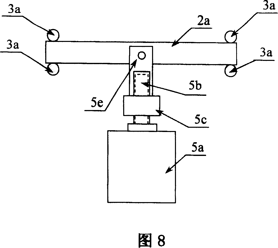
[0035] Fig. 4 is the second part structure of the device of the present in...


PUM


Abstract

The strain tuning device for dynamic chromatic dispersion compensation for grating includes one stress beam, one micro motor, one chirp fiber grating fixed on the side of the strain beam and one homogeneous fiber grating fixed on to the top of the strain beam. The homogeneous fiber grating has its one end connected to one wide band light source and one demodulating homogeneous fiber grating via a fiber coupler and the other end connect to a PC via a receiver. The other end of the demodulating homogeneous fiber grating is also connected to the PC, and the output of the PC is connected to the micro motor via a driver. The present invention adopts simple and cheap elements, the fiber grating for monitoring and the chirp fiber grating for chromatic dispersion compensation are fixed on the same tuning mechanism. The measured data are direct and reliable, and device is easy to control.

Description

Technical field: [0001] The invention relates to the technical field of optical communication, in particular to a strain-tuned optical fiber grating dispersion dynamic compensation and monitoring device and method thereof, which are mainly used for dispersion compensation in high-speed optical fiber communication. Background technique [0002] In a high-speed optical fiber communication system, due to the dispersion of the group velocity of light in the optical fiber, the pulse width of the optical signal expands during transmission, resulting in a decrease in the signal-to-noise ratio and an increase in the bit error rate. This is one of the most important factors affecting the working distance and data rate of a communication system. Therefore, fiber dispersion must be compensated. Due to factors such as different data rates, different data formats, and different transmission distances in communication systems, dispersion compensation is also required to be dynamically ad...

Claims


Application Information

Patent Timeline
Patent Type & Authority Patents(China)
IPC IPC(8): G02B6/26G02B6/34H04B10/17G06F3/00H04B10/2525
Inventor 方祖捷瞿荣辉蔡海文陈高庭
Owner SHANGHAI INST OF OPTICS & FINE MECHANICS CHINESE ACAD OF SCI
Features
  • R&D
  • Intellectual Property
  • Life Sciences
  • Materials
  • Tech Scout
  • Unparalleled Data Quality
  • Higher Quality Content
  • 60% Fewer Hallucinations
Learn More