Integrated component

A technology of integrated components and switching elements, which is applied in the field of integrated components, can solve the problems of increasing workload and reducing, and achieves the effect of simple design and elimination of cross effects

Inactive Publication Date: 2008-04-02
CONTINENTAL TEVES AG & CO OHG
View PDF3 Cites 0 Cited by
  • Summary
  • Abstract
  • Description
  • Claims
  • Application Information

AI Technical Summary

Problems solved by technology

[0005] However, such protection of an open path by a diode requires increased effort in manufacturing and assembly, and reduces the "pull-down" effect due to the voltage drop across the diode

Method used


Image

  • Integrated component

Examples


Embodiment Construction

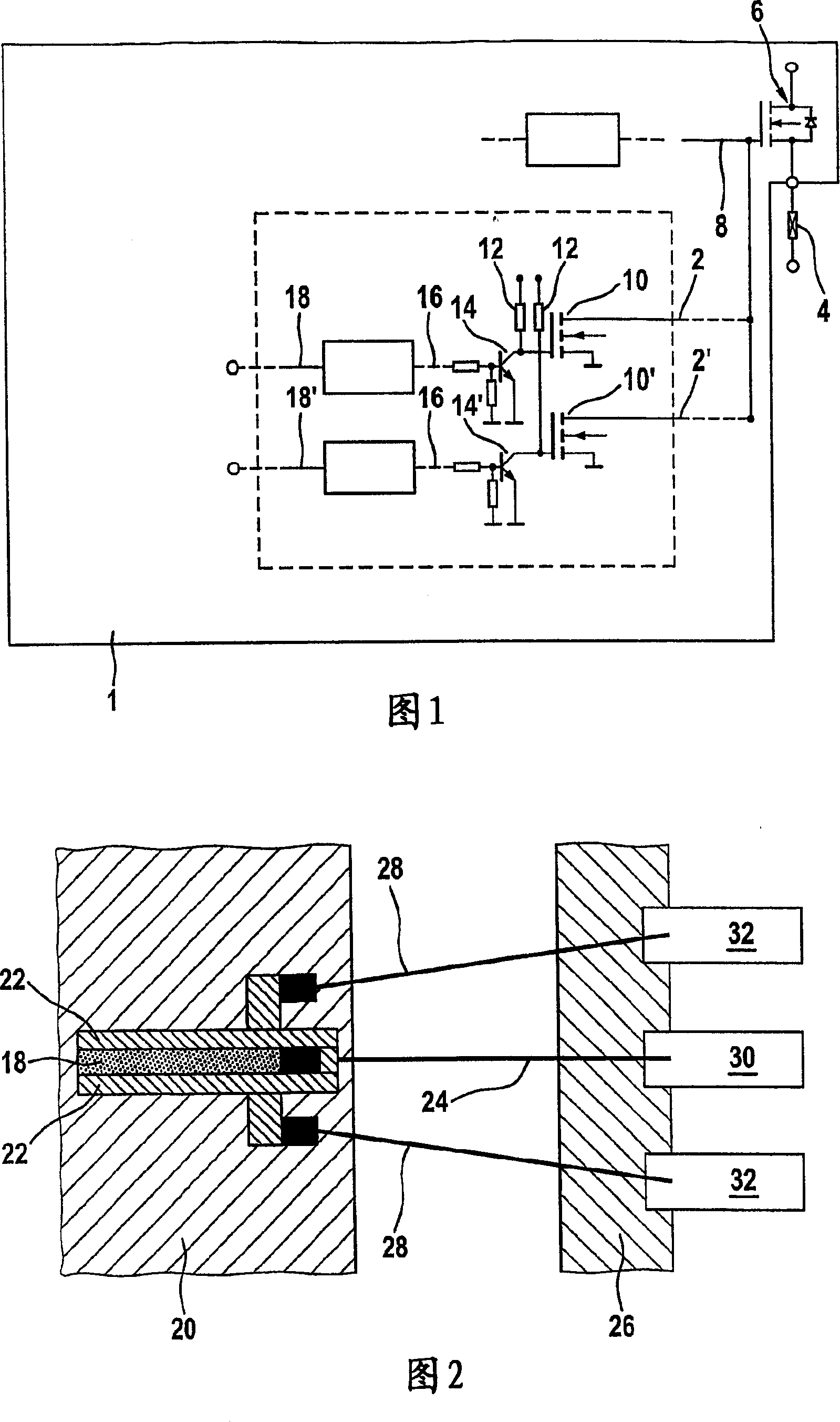
[0019] The integrated assembly 1 shown schematically and in part in FIG. 1 is used to switch off the voltage source of the valve stage associated with the brakes of the motor vehicle if necessary for safety reasons. For this purpose, the integrated assembly 1 comprises a redundantly designed disconnection path 2, 2' via which the driver output 8, which is used to activate the valve stage 4, can be grounded if required. Associated driver 6 voltage source. There can of course also be multiple load drivers, load and disconnection stages.

[0020] The disconnect paths 2, 2' operate without switches and each comprise a semiconductor switching element 10, 10' designed as a so-called "pull-down" transistor to perform a switching function when required. The constant voltage 12 turns on the semiconductor switching element. A further semiconductor switching element 14, 14' is connected to each upstream of the semiconductor switching elements 10, 10' within the disconnection path 2, 2'...


PUM


Abstract

The invention relates to an integrated component (1) which can more particularly be used to connect or disconnect load drivers in a motor vehicle braking system for safety reasons. Said component comprises a plurality of semiconductor switch elements (10, 10', 14, 14') and is constructed in a highly simple manner, offering a particularly high degree of operational reliability. According to the invention, the semiconductor switch elements (10, 10', 14, 14') are associated with control strip conductors (2, 2', 18, 18') which are surrounded by protection areas (22) which can be kept at a given reference potential.

Description

technical field [0001] The invention relates to an integrated assembly, arranged in particular in an integrated circuit, to drive a load in an electronic controller of brakes of a motor vehicle. Background technique [0002] Electronic braking systems can be used to control the brakes of motor vehicles, wherein valve coils associated with individual brakes are braked by means of integrated circuits, mainly using field effect transistors. When such a system fails, it is usually necessary to perform safety cut-off because the system is closely related to driving safety. In order to ensure this disconnection to a particularly high degree of reliability, its functional components are usually additionally protected with redundant circuits. For example, the driver output of such a system provided for actuating the voltage source of the mentioned valve stage is generally connected in such a way that two disconnect paths with a fully redundant design allow the driver to The output...

Claims


Application Information

Patent Timeline
Patent Type & Authority Patents(China)
IPC IPC(8): H01L27/12H01L23/52B60Q11/00B60LB60L1/00B60T8/00B60T8/78B60T17/00B60T17/18H01L23/552H01L23/62H01L27/02
CPCH01L2924/01032H01L2924/01082H01L2924/19043H01L2924/01004H01L24/48H01L2924/01068H01L23/552H01L2223/6611H01L2224/48227H01L2924/14H01L2924/01033H01L2924/01052H01L2924/01075H01L2224/49171H01L2924/30107H01L2924/3025H01L24/49H01L27/0248H01L23/62H01L2224/023H01L2924/00014H01L2924/1306H01L2924/00H01L2224/45099H01L2224/05599H01L2924/0001B60T8/00B60T8/72B60T17/00B60T17/18
Inventor W·法伊M·恩格尔曼G·赫茨尔
Owner CONTINENTAL TEVES AG & CO OHG
Why Eureka
Try Eureka