
Cold box for cryogenic distilling plant

A technology of low-temperature distillation and distiller, which is applied in household refrigeration equipment, applications, household appliances, etc., and can solve problems such as personnel evacuation

Inactive Publication Date: 2008-04-23
LAIR LIQUIDE SA POUR LETUDE & LEXPLOITATION DES PROCEDES GEORGES CLAUDE
View PDF4 Cites 2 Cited by
  • Summary
  • Abstract
  • Description
  • Claims
  • Application Information

AI Technical Summary

Problems solved by technology

But the safety issues stated above had to be addressed because the distillation unit was fixed to the metal structure and personnel could not be quickly evacuated from around the unit

Method used


Image

  • Cold box for cryogenic distilling plant

Examples


Embodiment Construction

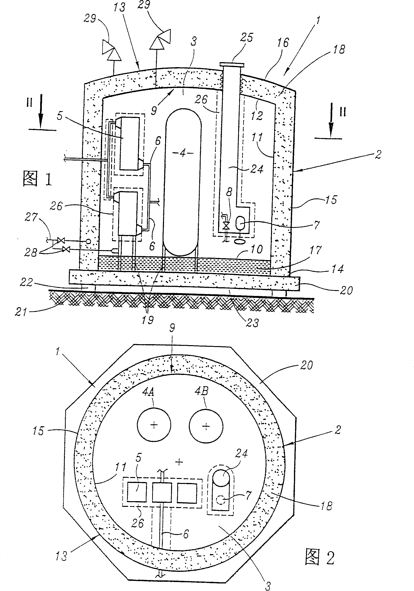
[0023] [23] The air distillation device 1 shown in Fig. 1 and Fig. 2 mainly includes a double-walled hood 2, and in the inner space 3 of the hood, double air distillation towers 4, heat exchangers 5, connecting pipes 6 and cryogenic Accessories, such as cryopump 7, cryogenic valve 8, etc.

[0024] [24] As in the prior art, column 4 consists of two distillation columns, one for medium pressure and one for low pressure. As shown in FIG. 2, the two columns 4A and 4B are placed side by side, but in FIG. 1 they are centered for clarity. Furthermore, the distillation unit naturally includes the full range of commonly used accessories and equipment.

[0025] [25] Cover 2 is a double shell. The inner shell 9 includes a flat bottom 10, a cylindrical side wall 11 and a dome 12, and is made of stainless steel. The housing 13 includes a flat bottom 14, cylindrical side walls 15 and a dome 16, and is made of carbon steel. But the bottom 14 can also be made of stainless steel.

[0026]...


PUM


Abstract

The distillation unit includes at least one cryogenic distilling column and at least one heat exchanger, arranged in a chamber with a double casing in which the intermediate partition contains a solid insulator. The unit can be on board offshore floating terminals and drilling platforms.

Description

technical field [0001] [01] The present invention relates to a cryogenic distillation plant, in particular for distillation of air, comprising a still having at least one cryogenic distillation column and at least one heat exchanger, and comprising thermal insulation of the still. It is used, for example, in oxygen generators installed on offshore oil platforms or ships. Background technique [0002] [02] Document US-A-4038060 has introduced a kind of cryogenic distiller of radioactive gas, and it surrounds the double wall filled with perlite around the distiller, and uses adsorbent in the inner shell to in case of accident Absorbs radioactive gases to prevent dangerous leaks. [0003] [03] In traditional technology, the cryogenic distillation tower and all related equipment (heat exchangers, cryopumps, cryogenic valves, connecting pipes, etc.) for low temperature operation are placed in a "cold shell" generally in the shape of a parallelepiped. Filled with bulk insulation...

Claims


Application Information

Patent Timeline
IPC IPC(8): F25J3/04F25D23/06F25J3/00F25J3/02
CPCF25J3/04975F25J3/04872F25J3/04878F25J3/04987F25J3/04945F25J2290/70F25J3/0489
Inventor 罗杰·范考文贝格让-皮埃尔·古尔比耶洛朗·巴朗热
Owner LAIR LIQUIDE SA POUR LETUDE & LEXPLOITATION DES PROCEDES GEORGES CLAUDE
Learn More