Overcurrent tester of TCR

A thyristor valve and test device technology, which is applied in the direction of measuring device, output power conversion device, measuring electricity, etc., can solve the problems of poor equivalent performance, low test parameters of the test circuit, and poor equivalence of the overcurrent test device, etc., to achieve Effects of safety control functions, improved test equivalence, and improved test parameter capabilities

Active Publication Date: 2008-06-04
CHINA ELECTRIC POWER RES INST +1
View PDF3 Cites 1 Cited by
  • Summary
  • Abstract
  • Description
  • Claims
  • Application Information

AI Technical Summary

Problems solved by technology

However, due to various reasons, the overcurrent test devices have some problems of poor equivalence, inflexible adjustment and failure to meet IEC standards:
[0009] Although the test circuit of SIEMENS company can meet the requirements of the two tests, the frequency is fixed when used to test the TSC, and the circuit parameter adjustment is very inconvenient. When the voltage is applied after the overcurrent, the reverse recovery overshoot is not also added to the test. On the product valve, this does not meet the requirements of the IEC standard;
[0010] The test parameters of TOSHIBA's test circuit are low, and the temperature of the test valve will drop quickly when switching with a switch, and the equivalent performance is even worse
[0011] As far as the country is concerned, although this field has great application prospects, it is still blank due to various reasons.

Method used


Image

  • Overcurrent tester of TCR
  • Overcurrent tester of TCR
  • Overcurrent tester of TCR

Examples


Embodiment Construction

[0031] The present invention will be further described below in conjunction with the accompanying drawings and embodiments.

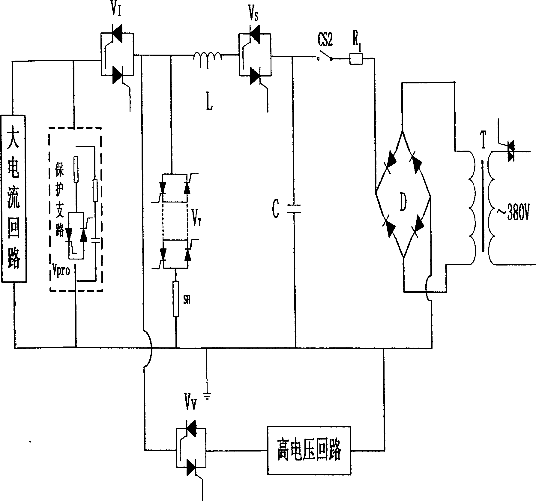
[0032] Such as figure 1 As shown, the test circuit is composed of five parts: a large current circuit as a large current source, a resonant circuit and a high voltage circuit, a charging circuit and a protection branch. The high current source provides heating current, the resonant circuit provides overcurrent and corresponding blocking voltage, and the high voltage circuit assists in realizing the special test requirements of HVDC valves. Heated auxiliary valve V I , used to control the heating current of the sample valve; the auxiliary valve V of the resonant circuit S , used to control the voltage on the sample valve and the overcurrent passing through; the high voltage loop auxiliary valve V V , used to control the auxiliary test voltage applied to the sample valve; V T is the test valve. Different test current frequencies can be generated by ...


PUM


Abstract

The invention relates to a thyristor valve over current testing device that the heavy current power supply to supply heating current to the testing circuit and the resonant tanic supplies over current and the corresponding blocking voltage, and the high voltage circuit assistants to realize the special demand for HVDC valve. By adjusting the combining of different capacitances and reactance of the resonant tanic, the testing current frequency and other current wave parameters would be generated. The second monitoring and adjusting system is made up of plural processing units and realizes collecting and monitoring to plural monitoring parameters through layer type structure. The inside of the system adopts CAN bus to realize data sharing channel and improve the reliability and flexibility of the system.

Description

technical field [0001] The invention relates to a test device for a thyristor valve in a power system and a power electronic system, in particular to a high-power power electronic device thyristor valve overcurrent test device. Background technique [0002] With the development of the national economy, the power industry development strategy of "power transmission from west to east, mutual supply from north to south, and national networking" has been implemented. How to greatly improve the utilization efficiency of power grid resources, overcome the bottleneck of power transmission and distribution, and realize the optimal allocation of power system resources while ensuring the safe and stable operation of the power grid has become a strategic technical problem that needs to be solved urgently. Flexible AC Transmission System (Flexible AC Transmission System, hereinafter referred to as FACTS) and DC transmission (High Voltage Direct Current, hereinafter referred to as HVDC) ...

Claims


Application Information

Patent Timeline
Patent Type & Authority Patents(China)
IPC IPC(8): G01R31/00H02M7/155
Inventor 贺之渊汤广福邓占锋雷晰李志麒
Owner CHINA ELECTRIC POWER RES INST
Why Eureka
Try Eureka