Control device of permanent magnetic contactor

A technology for control devices and contactors, applied in emergency protection circuit devices, relays, non-polar relays, etc., can solve problems such as coil burnout, power consumption, and large working current, and achieve the effects of strong breaking capacity, material saving, and simple structure

Inactive Publication Date: 2008-06-04
SOUTHEAST UNIV
View PDF4 Cites 0 Cited by
  • Summary
  • Abstract
  • Description
  • Claims
  • Application Information

AI Technical Summary

Problems solved by technology

When the coil is energized and closed, on the one hand, it consumes electric energy. Due to the large operating current during operation, the electric energy is lost in the hysteresis, eddy current and short-circuit ring, and most of the active power consumption of the coil is lost as heat; on the other hand, it will often Coil burning occurs
When the power supply voltage is too low, the electromagnetic force will be significantly reduced; when the AC current is zero, under the action of the return spring, the moving iron core of the contactor and the main contact will vibrate strongly, which will not only shorten the service life of the contactor, but also will affect the reliability of power supply

Method used


Image

  • Control device of permanent magnetic contactor
  • Control device of permanent magnetic contactor
  • Control device of permanent magnetic contactor

Examples


Embodiment Construction

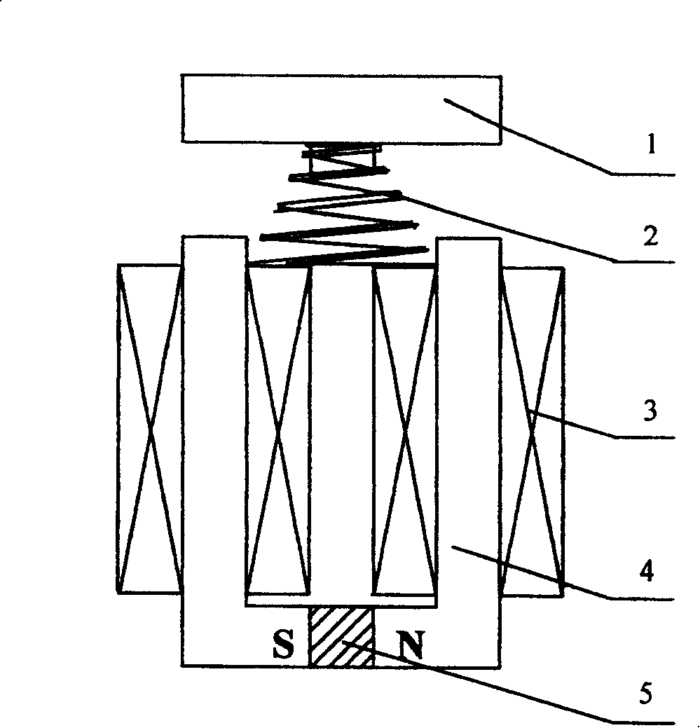
[0017] The permanent magnet contactor of the present invention is made up of moving iron core 1, static iron core 4, permanent magnet steel 5, coil 3, tower spring 2 and control circuit, is characterized in that: between two static iron cores 4, set There is a permanent magnetic steel 5, so that two static iron cores 4 and a permanent magnetic steel 5 form a "U"-shaped whole, and there is a coil 3 on each of the left and right static iron cores 4, and the phase between the two coils 3 They are connected in series and have the same polarity direction; the tower spring 2 is supported on the skeleton of the coil 3; the upper end of the tower spring 2 is connected with the moving iron core 1. The moving iron core 1 and the static iron core 4 are made of common electrical pure iron, and the permanent magnet 5 adopts NdFeB material with high magnetic energy product.

[0018] Such as figure 1 As shown, when the switch is closed, the coil passes a positive current, which is consisten...


PUM


Abstract

A permanent magnetic contactor and its control device are used in starting switch control devices and engines and switching on and off the master circuit. A permanent magnetic steel is set between two static cores to form a U-like bulk, two iron cores connected in series and in a same polarity, a tower spring supports the framework of the packet, the top of the tower spring is connected with a dynamic core. The output over voltage protection part of said control device is connected with the rectification part, output of which is connected with a low-voltage judgment part the output of which is connected with a shut off executing part and the output of which is connected with the wire packet.

Description

technical field [0001] The invention relates to a control device of a permanent magnet contactor, which is used for switching equipment, control equipment and motor starting, and performs closing and opening operations on a main circuit, belonging to the technical field of contactor manufacturing. Background technique [0002] Traditional contactors use electromagnetic coils to generate magnetic fields to maintain the pull-in state of the contacts. When the coil is energized and closed, on the one hand, it consumes electric energy. Due to the large operating current during operation, the electric energy is lost in the hysteresis, eddy current and short-circuit ring, and most of the active power consumption of the coil is lost as heat; on the other hand, it will often Coil burnout occurs. When the power supply voltage is too low, the electromagnetic force will be significantly reduced; when the AC current is zero, under the action of the return spring, the moving iron core o...

Claims


Application Information

Patent Timeline
Patent Type & Authority Patents(China)
IPC IPC(8): H01H51/01H01H47/02H02H7/22
Inventor 林鹤云房淑华
Owner SOUTHEAST UNIV
Why Eureka
Try Eureka