
Liquid bearing module

A fluid bearing and bearing technology, applied in the direction of bearings, shafts and bearings, mechanical equipment, etc., can solve the problems of rotating parts and fluid bearing lubricating medium easily flowing to the outside of the fluid bearing, so as to prevent the shaft from detaching and prevent the flow to the outside of the fluid bearing. external effects

Inactive Publication Date: 2008-06-18
IND TECH RES INST
View PDF7 Cites 0 Cited by
  • Summary
  • Abstract
  • Description
  • Claims
  • Application Information

AI Technical Summary

Problems solved by technology

[0007] The technical problem to be solved by the present invention is to provide a fluid bearing module to solve the problem of the fixed position between the rotating parts and the fluid bearing and the problem that the lubricating medium easily flows to the outside of the fluid bearing

Method used


Image

  • Liquid bearing module
  • Liquid bearing module
  • Liquid bearing module

Examples


Embodiment Construction

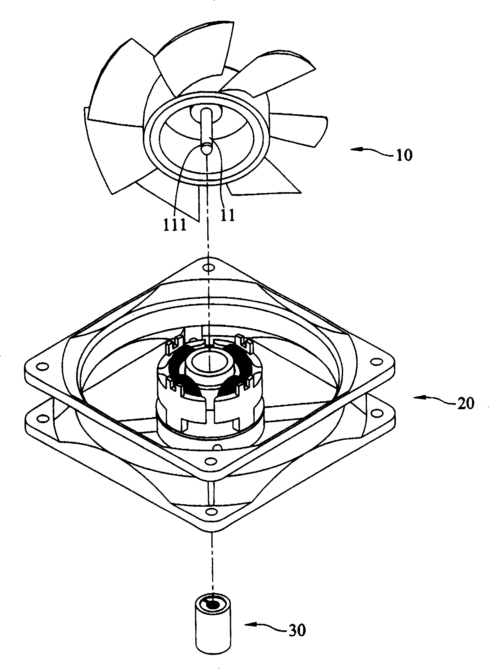
[0042] Such as image 3 As shown, a fluid bearing module 30 disclosed in the present invention is applied to an electric motor that outputs rotational kinetic energy such as a motor or a fan. Such as image 3 The fan shown includes a rotor part 10, a stator part 20 and a fluid bearing module 30, the rotor part 10 is arranged on the stator part 20 by using the fluid bearing module 30, and the rotor part 10 includes several blades arranged on the periphery, And the inner ring is provided with a permanent magnet, and is fixed on the center of the stator part 20 by using the shaft center 11 to install the fluid bearing module 30, and the stator part 20 has several magnetic poles formed by coils wound on several silicon steel sheets. After the current passes through the coil, the magnetic poles will generate magnetic force, so that the magnets correspond to the magnetic poles of the stator part 20. When the magnetic poles generate magnetic force, they will repel the magnets and make...


PUM


Abstract

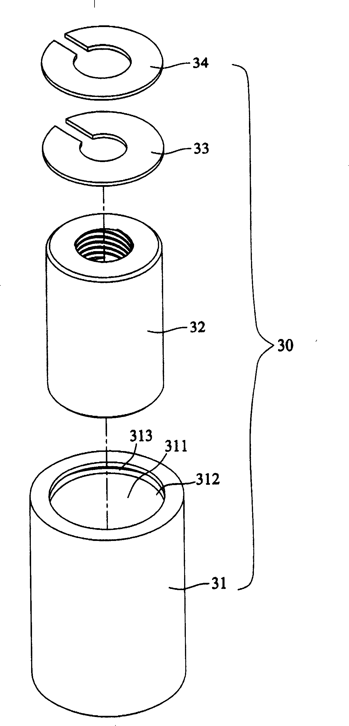
The invention discloses a kind of fluid bearing die block. It includes bearing seat, bearing, flex component, and pressure-withstand component. The inner of the bearing seat has container-device space, and one side has an opening connected to it. The bearing is set in the container-device space and hollow; it can let the axle center of the rotor part penetrate selectively; and the lubricating medium is filled between the bearing and rotor part. The bent module is convex set on the side of the hatch opening of the bearing seat; it can bent to the container-device space and is fixedly gripped by the fillister of the axle center. The pressure-withstand component is set on the side of the hatch opening of the bearing seat and closed to the hatch opening to restrict the flex component to bent to the hatch opening to avoid separating from axle center; and the flex component and the pressure-withstand component are formed to labyrinth walkway to prevent the lubricating medium from flowing to the outside.

Description

technical field [0001] The invention relates to a bearing module applied to rotating parts, in particular to a fluid bearing module (FLUID BEARING MODULE). Background technique [0002] Bearings are used on rotating parts to complete the functions of providing support, reducing friction and bearing load. With the advancement of science and technology, the parts are getting smaller and more precise, and the demand for bearing precision is getting higher and higher. In this situation, relatively, the cost of the most commonly used ball bearings is also increasing. High, for example: when ball bearings are used on motors, the cost of ball bearings accounts for more than one-third of the total cost, so there is a problem of high miniaturization cost. Secondly, if the ball bearing is slightly defective, there will be problems such as high noise and insufficient precision during the rotation of the rotating parts. The instability of the optical drive makes it easy for the optica...

Claims


Application Information

Patent Timeline
Patent Type & Authority Patents(China)
IPC IPC(8): F16C32/06
Inventor 施文章黄晋兴张裕修
Owner IND TECH RES INST
Learn More