Method for producing heat pipes

A manufacturing method and technology of heat pipes, which are applied in the field of heat pipe manufacturing, can solve problems such as the inability to dissipate heat from electronic components, the volume of heat pipes, and the reduction in volume of electronic components, and achieve the effects of small space occupation, small volume, and satisfying volume

Inactive Publication Date: 2008-08-20
HONG FU JIN PRECISION IND (SHENZHEN) CO LTD +1
View PDF2 Cites 3 Cited by
  • Summary
  • Abstract
  • Description
  • Claims
  • Application Information

AI Technical Summary

Problems solved by technology

With the continuous improvement of the performance of electronic components such as central processing units, the calorific value is increasing. The traditional heat pipe has a contradiction between the large volume of the electronic components and the increasingly small volume of the electronic components, which cannot meet the heat dissipation requirements of the electronic components with high calorific value.

Method used


Image

  • Method for producing heat pipes
  • Method for producing heat pipes
  • Method for producing heat pipes

Examples


Embodiment Construction

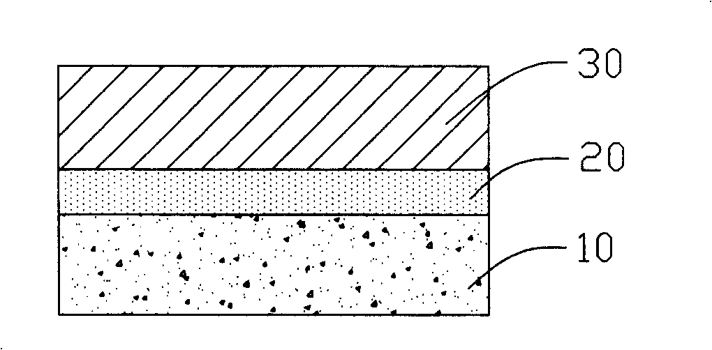
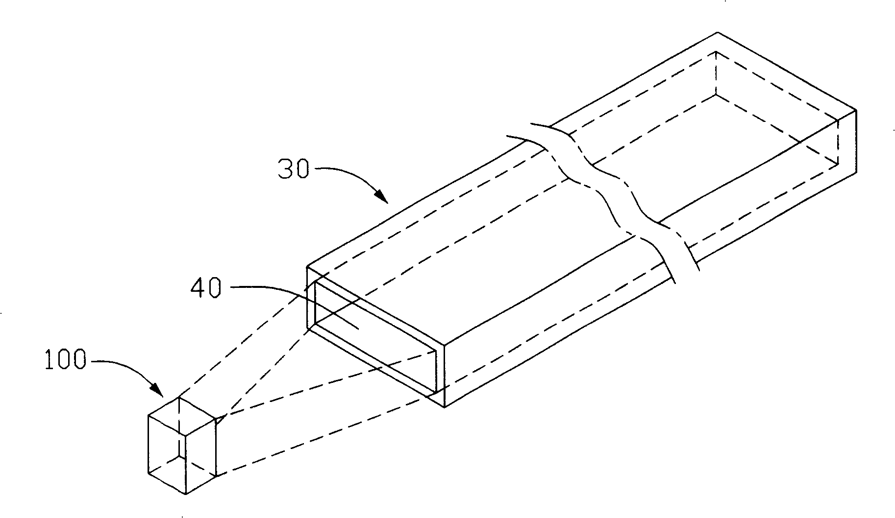
[0014] see Figure 1 to Figure 4 The heat pipe manufacturing method of the present invention is as follows: provide a substrate 10 (in the embodiment of the present invention, a silicon wafer is used as the substrate); and form a thin layer of silicon dioxide oxide layer 20 on the surface of the substrate 10 by dry oxidation. Place the above-mentioned substrate 10 with the oxide layer 20 attached on the surface on a vacuum coating machine, and apply an appropriate amount of photoresist attachment solution to evenly distribute it on the oxide layer 20 to form a photoresist layer 30 . After the coating is completed, place it on a heating plate for soft baking at a temperature of 90° C., so that the photoresist layer 30 changes from the original liquid state to a solid uniform film, so that the required photoresist layer 30 can be formed. Put the above-mentioned photoresist layer 30 on the stage of the exposure machine for exposure through the instrument 100, so as to transfer th...


PUM


Abstract

A manufacturing method for a thermal tube includes: providing a chip, forming an oxidation layer on the chip surface, adhering a photo resist layer on said oxidation layer, forming a channel on it, sealing the open-end of the channel, covering a layer of high polymer to form a case of the tube, opening an orifice on the case and the photo resist layer for letting working fluid in and filling in the orifice with solution then sealing the orifice.

Description

【Technical field】 [0001] The invention relates to a method for manufacturing a heat pipe, in particular to a method for manufacturing a heat pipe used for heat dissipation of heating electronic components. 【Background technique】 [0002] With the rapid development of the electronic information industry, the processing capacity of electronic components such as the central processing unit is increasing day by day, and the heat generated is increasing. The heat dissipation module combined with the heat sink and the fan has gradually been unable to meet the heat dissipation requirements, especially for notebook computers. At present, the heat pipe is an important component widely used in heat transfer. As a heat transfer device, the heat pipe is filled with an appropriate amount of working liquid in a sealed low-pressure metal shell with good thermal conductivity, and uses the principle that the working liquid absorbs or releases a large amount of heat when the working liquid is...

Claims


Application Information

Patent Timeline
Patent Type & Authority Patents(China)
IPC IPC(8): H01L23/427H05K7/20G06F1/20F28D15/02B81B5/00
Inventor 沈志华
Owner HONG FU JIN PRECISION IND (SHENZHEN) CO LTD
Why Eureka
Try Eureka