Engine-driven electric generator

An engine drive and generator technology, applied in engine components, engine control, machine/engine, etc., can solve the problems of increased weight, complex structure, and large number of parts, and achieve easy maintenance, simplified frame structure, and improved operability Effect

Inactive Publication Date: 2008-09-17
HONDA MOTOR CO LTD
View PDF7 Cites 0 Cited by
  • Summary
  • Abstract
  • Description
  • Claims
  • Application Information

AI Technical Summary

Problems solved by technology

Therefore, not only the number of parts is large and the structure is complicated, but also the weight increases

Method used


Image

  • Engine-driven electric generator
  • Engine-driven electric generator
  • Engine-driven electric generator

Examples


Embodiment 1

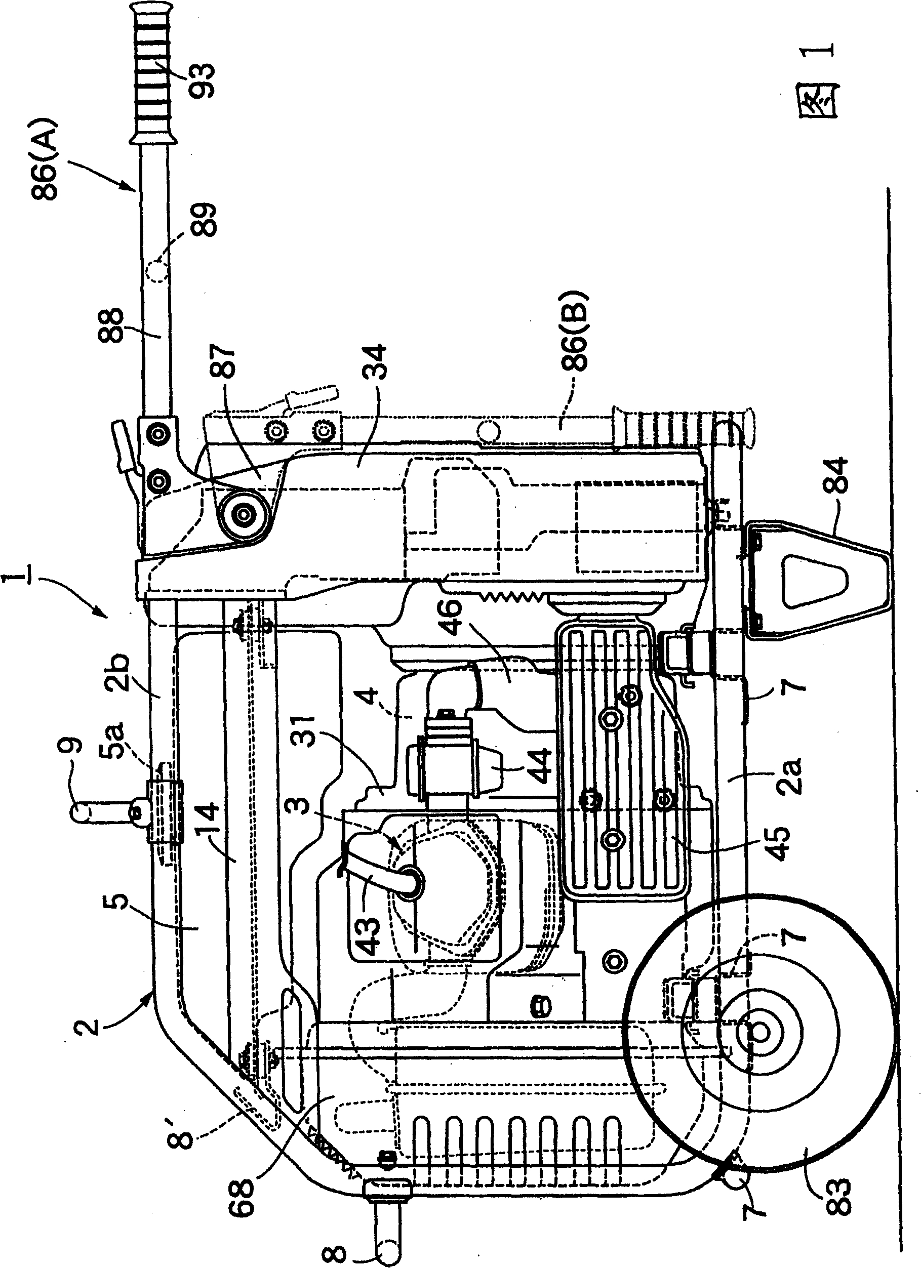
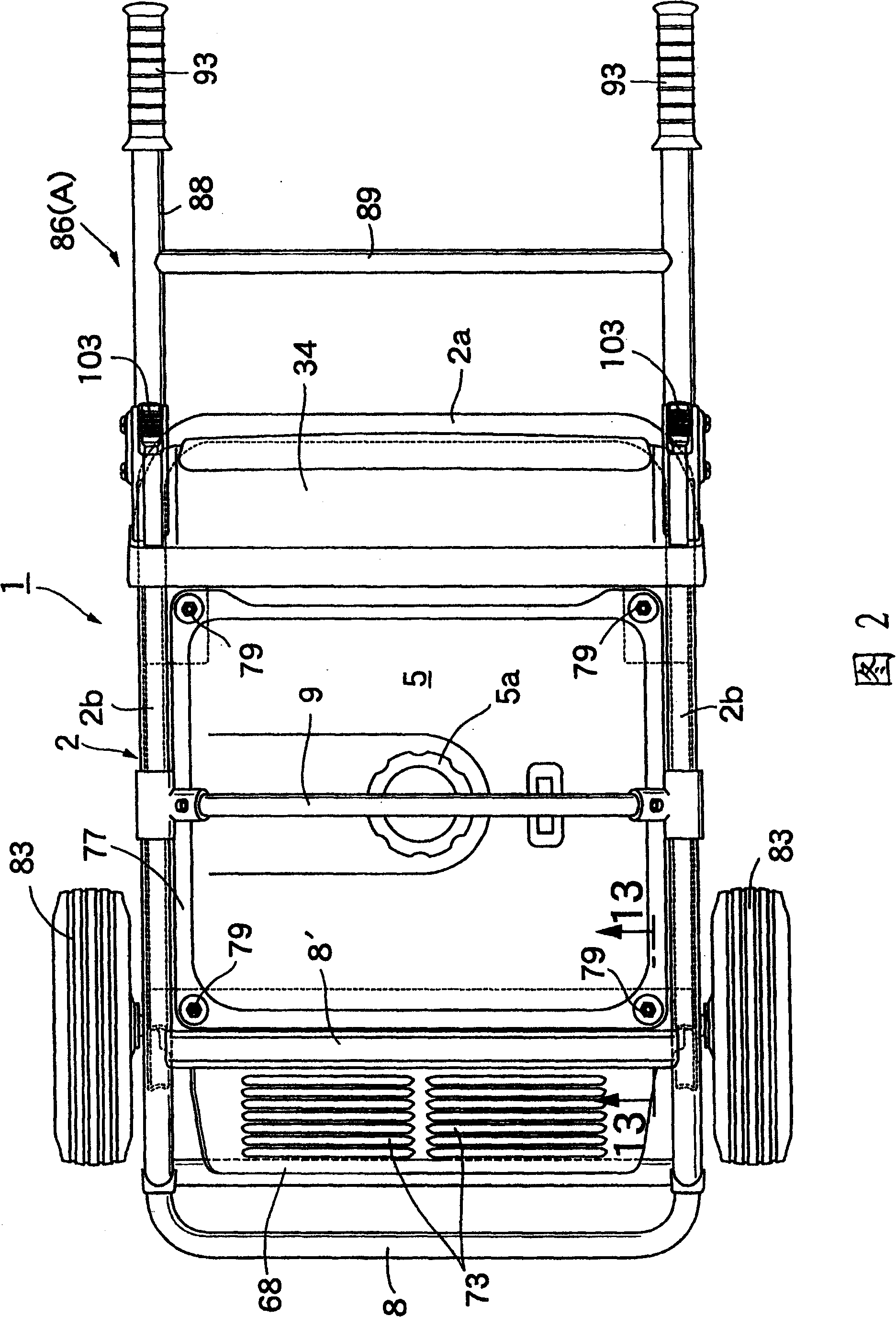
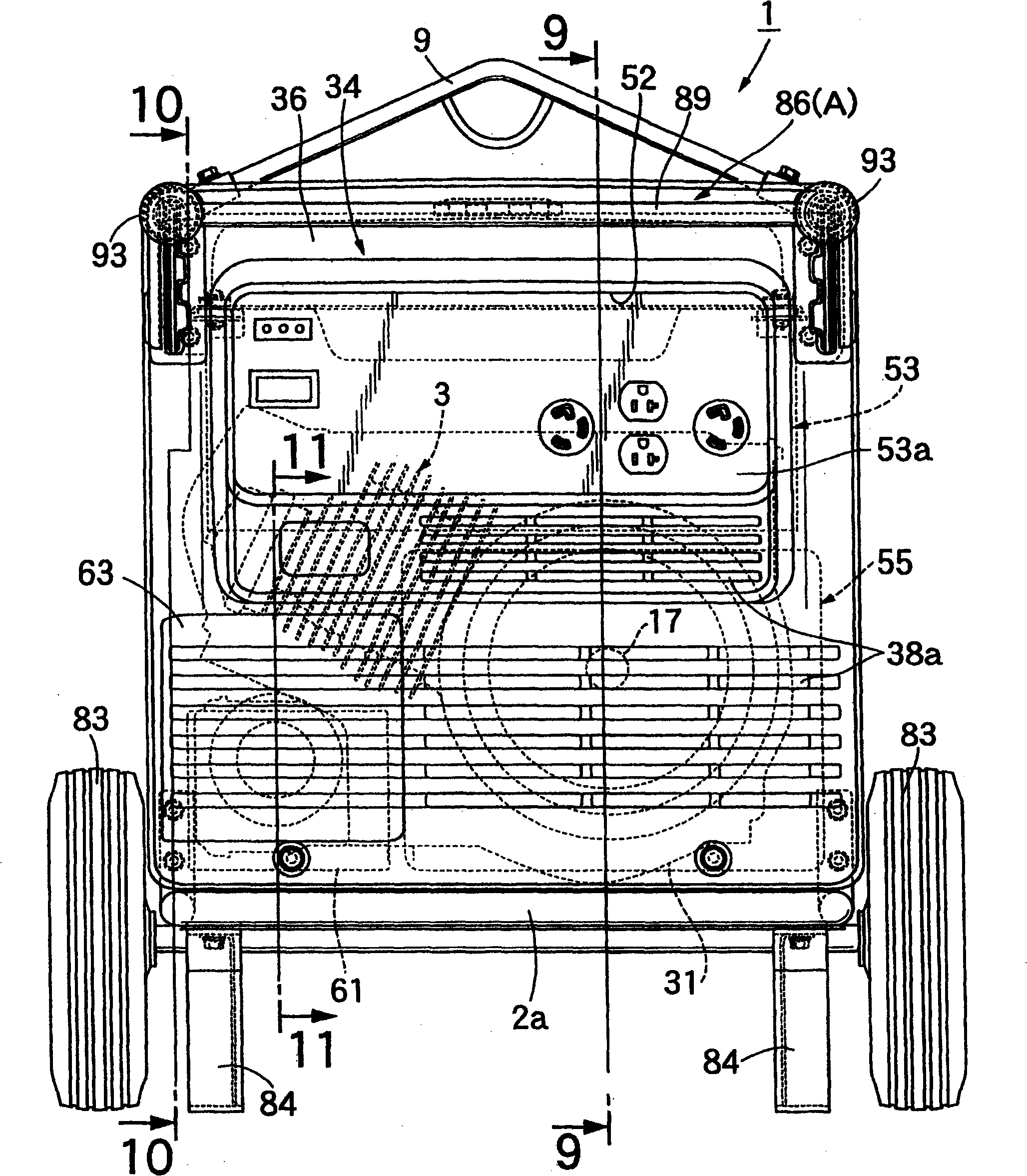
[0063] First in Figure 1~ image 3 Among them, the engine-driven generator 1 of the present invention has: a frame 2; an engine 3 and a generator 4 elastically supported at the bottom of the frame 2; a fuel tank 5 installed at the top of the frame 2; Control unit 53 of engine 3 and generator 4 .

[0064] Figure 1~ image 3 And as shown in FIG. 8, the frame 2 is constituted to include: a bottom frame 2a obtained by bending a steel pipe into a U-shape; The left and right sides of 2a cooperate to form U-shaped left and right side frames 2b, 2b.

[0065]A plurality of lower cross members (cross members) 7, 7 ... connected between the left and right sides are provided on the bottom frame 2a, and a connection is provided between the upper parts of the vertical sides of the two side frames 2b, 2b. The middle cross member 8 of the two side frames 2b, 2b is provided with an upper cross member 8' connecting the inclined corners above the two side frames 2b, 2b. The middle portion in t...


PUM


Abstract

An engine-driven generator is provided that is formed by supporting on a frame (2) an engine (3) and a generator (4) driven by the engine (3), wherein the frame is formed by integrally connecting via a cross member (7) lower side sections of a pair of left and right side frames (2b, 2b) formed by bending a steel pipe into a U-shape, a control box (34) housing and holding an electrical component (53, 55) is mounted on open end parts of the two side frames (2b, 2b) in order to reinforce the frame (2) by connecting the open end parts to each other, and an assembly of the engine (3) and generator (4) is resiliently supported on the cross member (7). The structure of the frame of the engine-driven generator can thereby be simplified, the frame can be reinforced by the control box that houses and supports the electrical component, and the frame can be made lightweight.

Description

technical field [0001] The present invention relates to improvements to engine-driven generators configured to support an engine and a generator driven by the engine on a frame. Background technique [0002] As such an engine-driven generator, for example, one disclosed in Document 1 below is known. [0003] Patent Document 1: Japanese Patent Application Laid-Open No. 11-36880 [0004] In the engine-driven generator disclosed in the above-mentioned Patent Document 1, its frame structure is composed of: a bottom frame; a front frame and a rear frame connected to and erected from the front and rear ends of the bottom frame; A pair of left and right reinforcing bars (rails) connecting the upper ends of the frame. Therefore, not only the number of parts is large and the structure is complicated, but also the weight increases. Contents of the invention [0005] The present invention is proposed in response to the above problems, and its purpose is to provide an engine-driven...

Claims


Application Information

Patent Timeline
Patent Type & Authority Patents(China)
IPC IPC(8): F02B63/04F02B77/00F02D29/06
CPCF02D29/06F02B63/047F02B63/04F02B2063/045
Inventor 广濑忠文浅井孝一
Owner HONDA MOTOR CO LTD
Why Eureka
Try Eureka