Hydraulic clamping apparatus for machine tool
A hydraulic clamping and lathe technology, applied in the field of machinery, can solve problems such as the hidden dangers that affect the machining accuracy and service life of the lathe, the appearance of the lathe is unsightly, unsafe, etc., to prevent slipping or falling off, beautiful appearance, and high clamping force. Effect
- Summary
- Abstract
- Description
- Claims
- Application Information
AI Technical Summary
Problems solved by technology
Method used
Image

Examples
Embodiment Construction
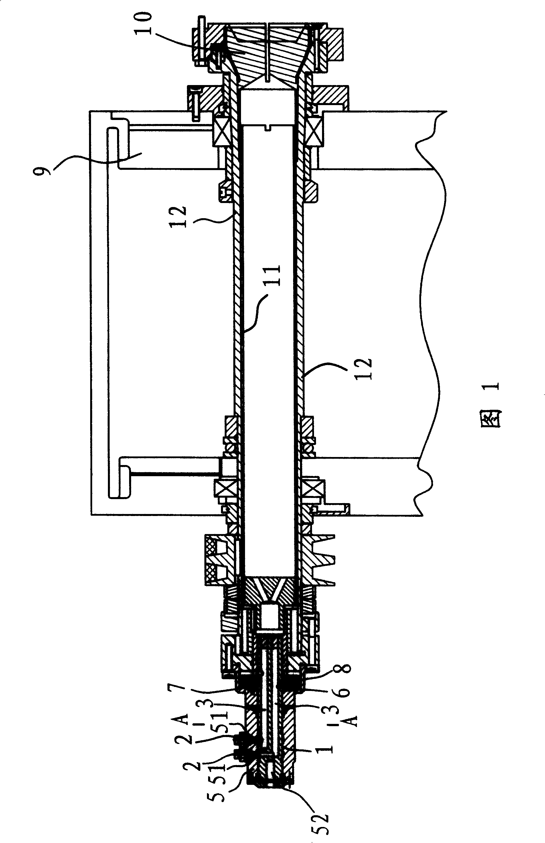
[0023] As shown in Figure 1, the hydraulic clamping device of the lathe is arranged at 9 places on the bedside box of the lathe. Head 10 compositions.
[0024] In this embodiment, the collet 10 and the drawing tube 11 are screwed together and installed in the main shaft 12 . The collet 10 is conical and is located at the end of the main shaft 12 . By moving the pull tube 11 back and forth, the main shaft 12 is squeezed or not pressed against the collet, so that the collet 10 is clamped or released from the workpiece.
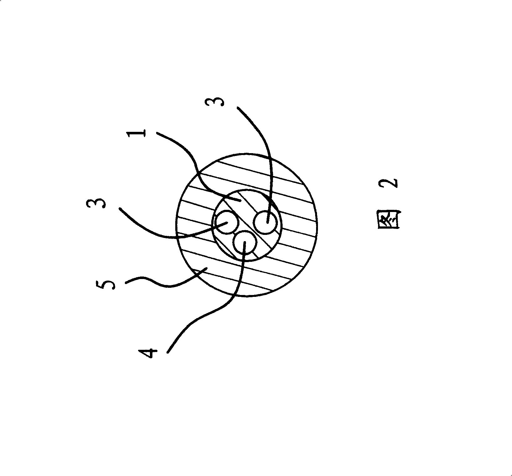
[0025] At the other end of the main shaft 12 there is a hydraulic cylinder 7 . The piston 8 in the hydraulic cylinder 7 is fixedly connected with the pull pipe 11. Therefore, the movement of the piston 8 will drive the pull tube 11 to move together. The mandrel 1 passes through the piston 8 , its outer end is inserted into the mandrel seat 5 , and its inner end is in the main shaft 12 .
[0026] As shown in FIG. 2 , there are two through holes 3 and one air...
PUM
 Abstract
Description
Claims
Application Information
 - R&D
- Intellectual Property
- Life Sciences
- Materials
- Tech Scout
- Unparalleled Data Quality
- Higher Quality Content
- 60% Fewer Hallucinations
Browse by: Latest US Patents, China's latest patents, Technical Efficacy Thesaurus, Application Domain, Technology Topic, Popular Technical Reports.
© 2025 PatSnap. All rights reserved.Legal|Privacy policy|Modern Slavery Act Transparency Statement|Sitemap|About US| Contact US: help@patsnap.com