Shaft current control brush assembly with drainage

A brush device, shaft current technology, applied in the direction of static electricity, circuit, current collector, etc., can solve the problems of time-consuming, non-continuous operation, drop, etc.

Active Publication Date: 2008-11-05
ILLINOIS TOOL WORKS INC
View PDF7 Cites 3 Cited by
  • Summary
  • Abstract
  • Description
  • Claims
  • Application Information

AI Technical Summary

Problems solved by technology

The disadvantage of using an AC motor with a variable speed drive is the high common mode voltage (CMV) generated by the variable speed drive, which increases the shaft induced current
Contaminants can enter the bearings on the spindle and can cause damage or performance degradation
Removing units for periodic cleaning is time consuming and impractical for substantially continuously operating equipment

Method used


Image

  • Shaft current control brush assembly with drainage
  • Shaft current control brush assembly with drainage
  • Shaft current control brush assembly with drainage

Examples


Embodiment Construction

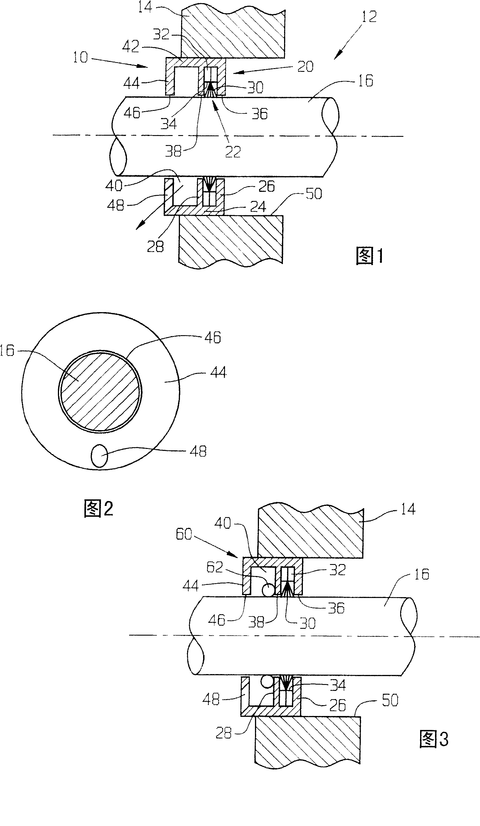
[0025] Referring now more particularly to the drawings and to FIG. 1 in particular, reference numeral 10 indicates a shaft current control brush ring arrangement according to the invention. The brush ring arrangement 10 is mounted on the electric motor 12 and in particular on the main shaft 14 of the electric motor 12 for dissipating electric charges that may accumulate on the main shaft 16 of the electric motor 12 . It should be understood that the brush ring assembly 10 may be provided in a variety of different sizes for use in different types of electric machines and on different diameter shafts 16 .

[0026] The brush ring arrangement 10 is generally annular to surround the main shaft 16 . Brush ring assembly 10 is secured to panel 14 and is operably mounted between spindle 16 and panel 14 to dissipate static or other charges that accumulate on motor spindle 16 during operation of motor 12 .

[0027] The brush ring arrangement 10 comprises an annular groove 20 and a brush...


PUM


Abstract

A shaft current control brush ring assembly includes a channel and a brush ring assembly secured within the channel. A drain is provided to direct liquids and contaminants away from said brush ring assembly.

Description

[0001] Cross-references to related applications [0002] This application claims priority to US Provisional Application No. 60 / 709021, filed August 17,2005. technical field [0003] The present invention relates generally to grounding devices, and more particularly to grounding devices for motor shafts, turbine shafts and other rotating shafts electrically connected to components that generate electrical charge or are subject to charge buildup. Background technique [0004] Shaft-induced currents are generated in electric motors, typically three-phase motors driven by variable speed drives. Variable speed drives use pulse width modulation to vary the speed of an AC motor, allowing inexpensive AC motors to be used in applications where more expensive DC motors were previously used. The disadvantage of using an AC motor with a variable speed drive is the high common mode voltage (CMV) generated by the variable speed drive, which increases the shaft induced current. [0005] ...

Claims


Application Information

Patent Timeline
Patent Type & Authority Patents(China)
IPC IPC(8): H01R39/24H01R39/46H01R39/48H05F3/00
Inventor 希扬·W.·欧
Owner ILLINOIS TOOL WORKS INC
Why Eureka
Try Eureka