Falling film evaporator having two-phase refrigerant distribution system

A falling-film evaporator, refrigerant technology, applied in the direction of evaporator/condenser, refrigerator, refrigeration components, etc., can solve the problems of increasing material cost of cooler, high cost, expensive and other issues

Inactive Publication Date: 2008-11-12
TRANE INT INC
View PDF9 Cites 0 Cited by
  • Summary
  • Abstract
  • Description
  • Claims
  • Application Information

AI Technical Summary

Problems solved by technology

Although it is convenient to distribute the refrigerant evenly by conveying only liquid refrigerant to distribute it to the tube bundles in the falling film evaporator in the RTHC cooler, due to the need for the refrigerant distributor in the evaporator A separate vapor-liquid separation element upstream of the cooler is therefore more costly and more expensive...

Method used


Image

  • Falling film evaporator having two-phase refrigerant distribution system
  • Falling film evaporator having two-phase refrigerant distribution system
  • Falling film evaporator having two-phase refrigerant distribution system

Examples


Embodiment Construction

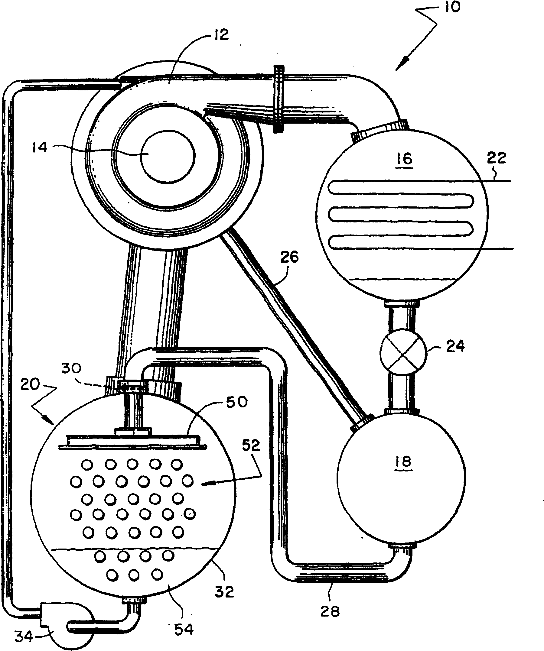
[0032] See first figure 1 , The main components of the chiller system 10 are: a compressor 12 driven by an electric motor 14 , a condenser 16 , an efficiency booster 18 and an evaporator 20 . These components are connected in series to allow refrigerant to flow in a basic refrigerant circuit, which will be more fully described hereinafter.

[0033] In the preferred embodiment, compressor 12 is a centrifugal compressor. It should be understood, however, that falling film evaporators and refrigerant distributors of the type described herein may also be considered in coolers in which the compressor is other than centrifugal and fall within this scope. within the scope of protection of the invention.

[0034] In general, high pressure refrigerant gas fed into condenser 16 is condensed into liquid form by heat exchange with a fluid, usually water, which is fed into said condenser through line 22 . As is the case in most chiller systems, a portion of the lubricant used inside the...


PUM


Abstract

Efficient two-phase refrigerant mixture distribution is accomplished in a falling film evaporator by use of a refrigerant distributor (50) disposed internal of the evaporator shell which overlies the evaporator tube bundle and which internally causes said two-phase refrigerant mixture to be made available along essentially the entire length and across essentially the entire width of the tube bundle prior to the delivery of the refrigerant out of the distributor.

Description

[0001] This application is a divisional application of the application No. 00804839.8, the application date is February 4, 2000, and the title is "falling film evaporator with two-phase refrigerant distribution system". technical field [0002] The present invention relates to the distribution of a two-phase refrigerant mixture within an evaporator of a refrigeration system. More particularly, the present invention relates to the uniform distribution of a saturated two-phase refrigerant to and across tube bundles in falling film evaporators used in refrigeration chillers. Background technique [0003] The main components of a refrigeration cooler include: a compressor, a condenser, an expansion device and an evaporator. High pressure refrigerant gas is passed from the compressor to a condenser which cools and condenses the refrigerant gas into a liquid state. Condensed refrigerant flows from the condenser to and through the expansion device. The passage of the refrigerant ...

Claims


Application Information

Patent Timeline
IPC IPC(8): F25B39/02F28D3/04
CPCY10S165/171F25B39/028F25B2339/0242F28D3/04F25B2500/01
Inventor J·P·哈特菲尔德S·A·莫伊肯斯J·W·拉森
Owner TRANE INT INC
Why Eureka
Try Eureka