
Acceleration sensor

An acceleration sensor, acceleration technology, applied in the measurement of acceleration, speed/acceleration/impact measurement, acceleration measurement using inertial force, etc., can solve the problems of inability to change materials, wear, mechanical deformation, etc., to achieve high reliability and high reliability Sex, long life effect

Inactive Publication Date: 2008-11-12
华南理工大学机械工程学院
View PDF7 Cites 0 Cited by
  • Summary
  • Abstract
  • Description
  • Claims
  • Application Information

AI Technical Summary

Problems solved by technology

[0006] The above-mentioned acceleration sensors all have mechanical contact, have mechanical deformation and wear, and cannot change the material once manufactured

Method used


Image

  • Acceleration sensor
  • Acceleration sensor
  • Acceleration sensor

Examples


Embodiment Construction

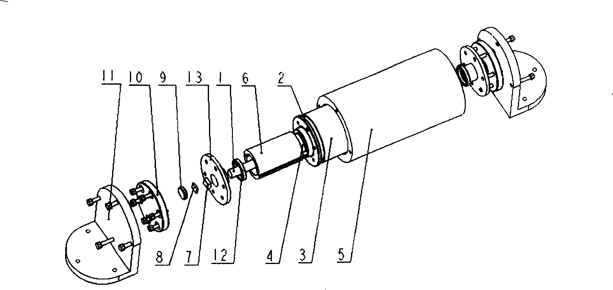
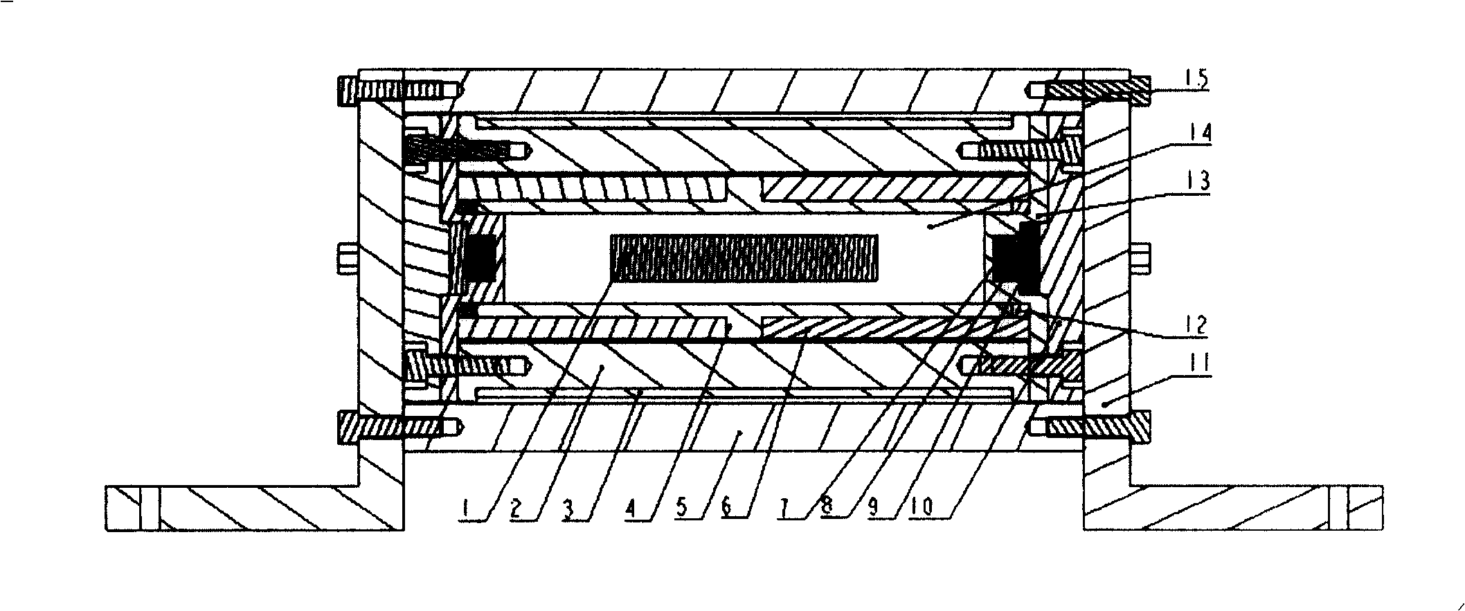
[0045] The core of the present invention is to place a magnetic moving part (that is, the magnetic float 1) in the inside of a closed container (that is, a non-magnetic cavity) full of magnetic fluid 14 composed of a non-magnetic material, because the magnetic float 1 itself There is a magnetic field gradient, and the magnetic fluid 14 generates a force under the action of the magnetic field gradient, so that the magnetic float 1 is suspended in the magnetic fluid 14, and maintains an intermediate equilibrium position in the radial direction of the non-magnetic cavity; when there is an acceleration, The position of the magnetic float 1 moves, and the detection device detects the displacement change of the magnetic float, and outputs an acceleration detection result signal.

[0046] The structure of the specific embodiment of the present invention is as figure 1 and figure 2 As shown: the most basic structure of the acceleration sensor includes: a non-magnetic cavity, a magne...


PUM


Abstract

This invention relates to one acceleration sensor, which puts one magnetic floater into one non-magnetic materials to form full magnetic fluid non-magnetic chamber, wherein, due to the magnetic floater self magnetic gradient, the magnetic fluid is under magnetic gradient to generate one force to make the floater float in the magnetic fluid and keep middle balance position along non-magnetic chamber radium; when there is acceleration, the magnetic floater move to output acceleration result signals through test device.

Description

technical field [0001] The invention relates to the field of production and application of acceleration sensors, in particular to an acceleration sensor based on magnetic fluid. Background technique [0002] At present, acceleration sensors are commonly used in many technical fields, such as automobile motion control, automobile testing, home appliances, game products, office automation, GPS, PDA, mobile phones, vibration detection, construction instruments and experimental equipment, etc. [0003] Existing acceleration sensors usually have the following structures. [0004] One is to place the steel ball in the casing in a freely movable state. According to the mechanical vibration applied from the outside, the steel ball moves relatively, and the switch part designed according to the predetermined configuration according to the displacement produces an on or off output. The structure is mainly used as an acceleration switch. [0005] Another type of acceleration sensor b...

Claims


Application Information

Patent Timeline
Patent Type & Authority Patents(China)
IPC IPC(8): G01P15/02G01P15/00
Inventor 刘桂雄曹东
Owner 华南理工大学机械工程学院
Learn More