Method and apparatus for removing dust from a workpiece

A technology for working elements and exit devices, applied in the attachments of sawing machines, metal processing machinery parts, manufacturing tools, etc., can solve the problems of hindering the users of the jig saw, hindering the visibility of the cutting line, and low efficiency.

Inactive Publication Date: 2008-11-26
BLACK & DECKER INC
View PDF8 Cites 0 Cited by
  • Summary
  • Abstract
  • Description
  • Claims
  • Application Information

AI Technical Summary

Problems solved by technology

But these known methods have the disadvantage that if the blower or suction is placed too close to the saw blade it hinders the jigsaw user and if it is too far from the saw blade it is not very effective
Also, by blowing debris in the direction of the tool's line of action, debris may be blown onto the tool's cutting line, which will interfere with the visibility of the cutting line and subsequent cutting action

Method used


Image

  • Method and apparatus for removing dust from a workpiece
  • Method and apparatus for removing dust from a workpiece
  • Method and apparatus for removing dust from a workpiece

Examples


Embodiment Construction

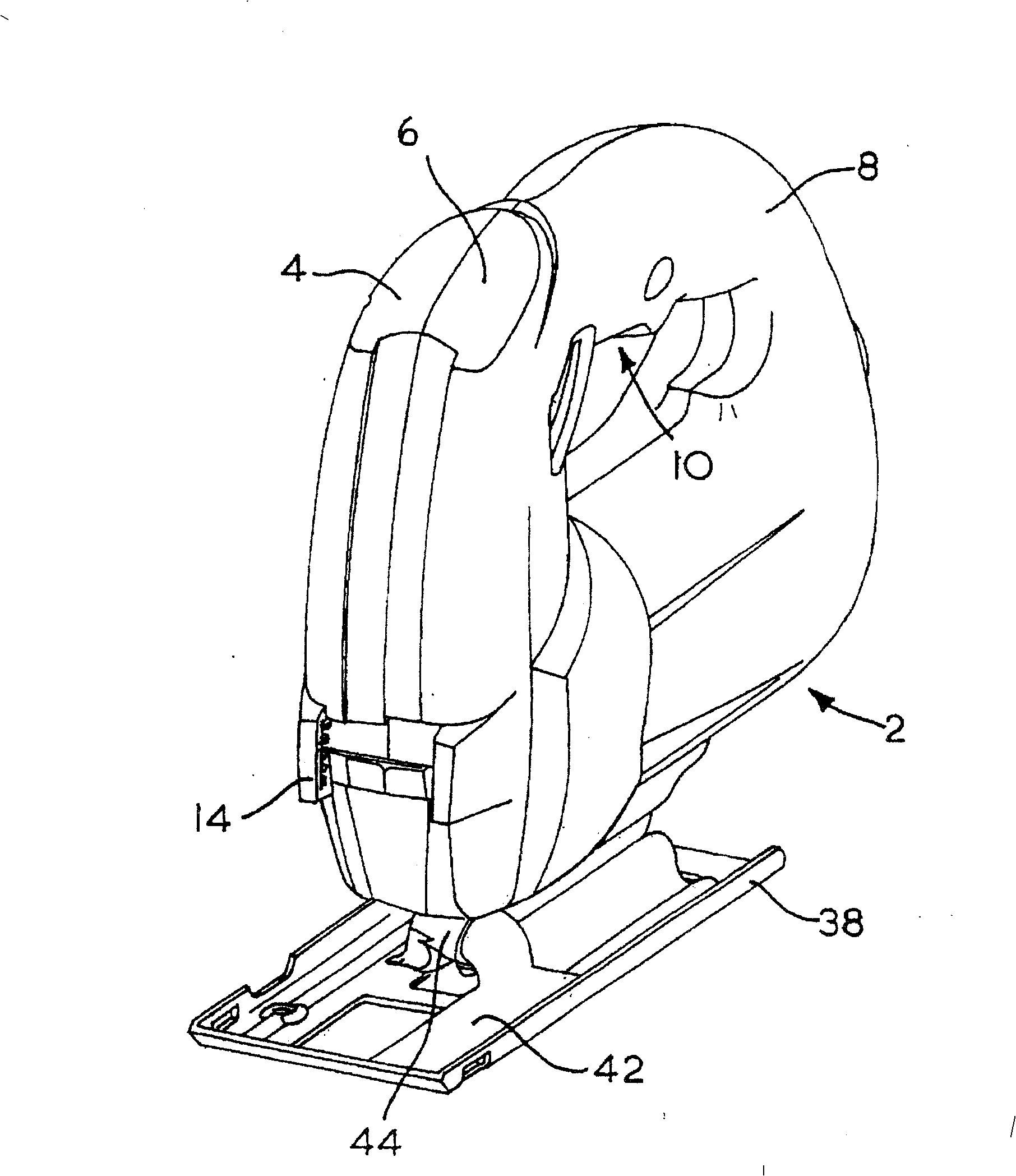
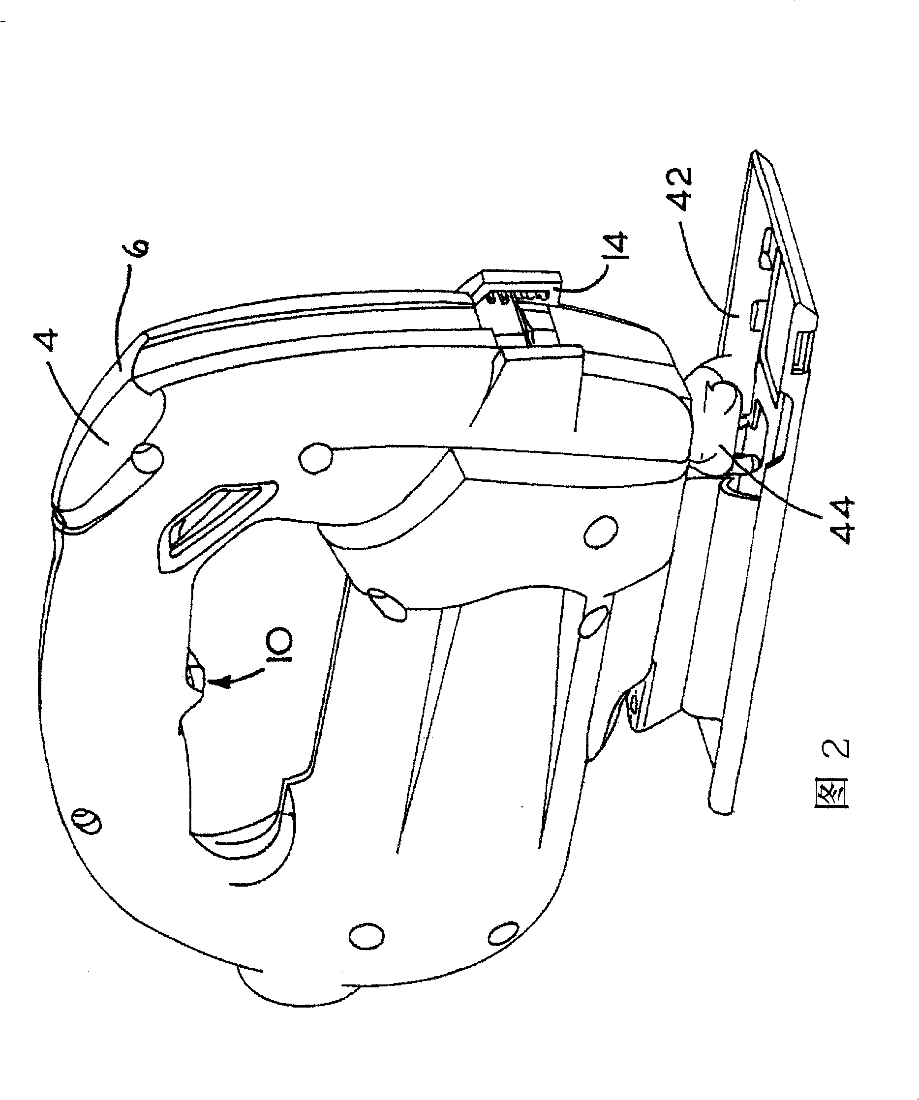
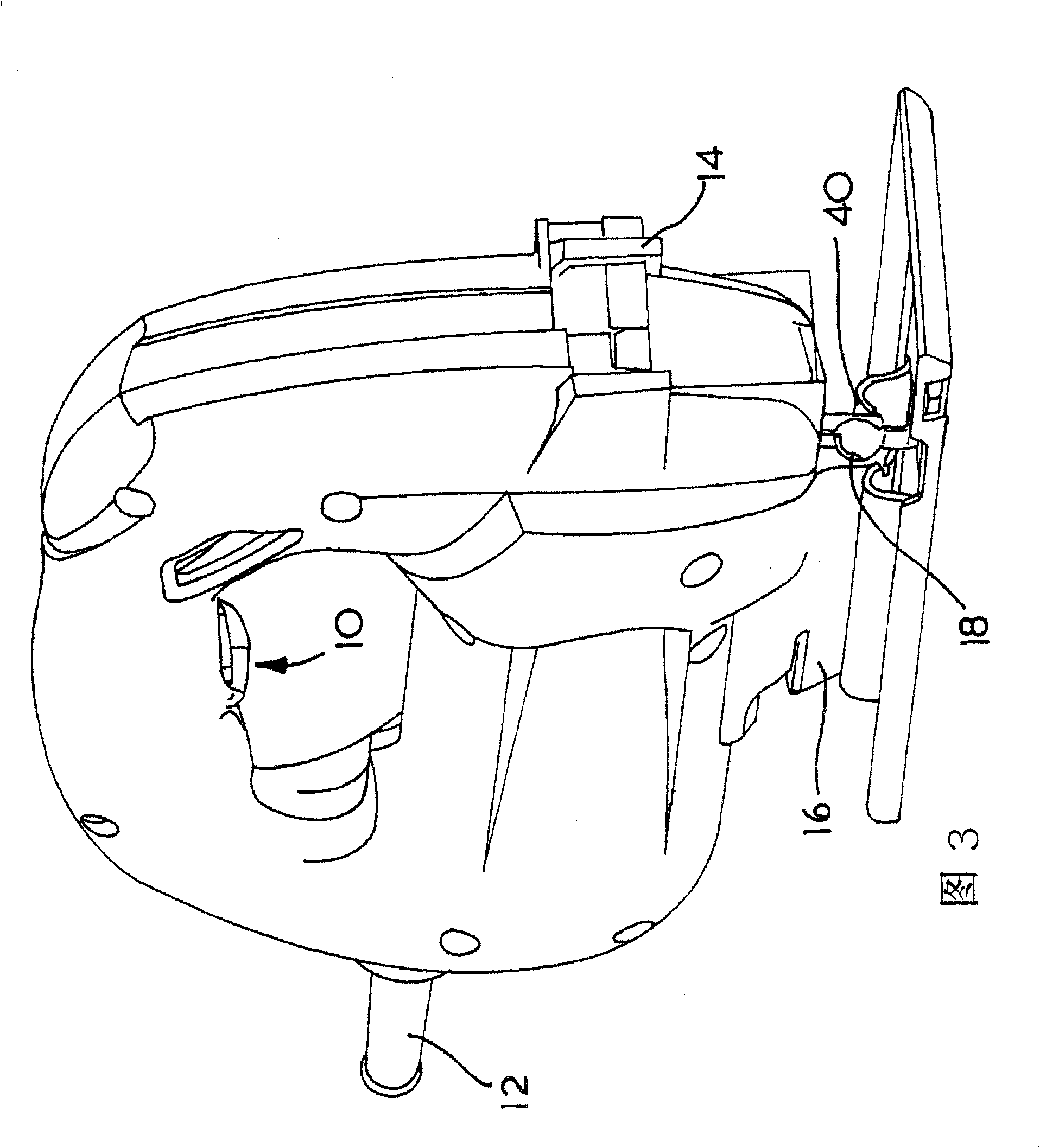
[0039] refer to Figure 1 to Figure 4 , the jigsaw 2 has a housing in the form of a clamshell consisting of two halves 4 , 6 . The jigsaw 2 forms a handle portion 8 to be grasped by the user and defines an area 10 in which a trigger (Fig. 7) is formed enabling the user to activate the jigsaw 2 to cut a workpiece (not shown).

[0040] Power is supplied to the jigsaw 2 via a power cord 12 (FIG. 3). The saw blade protection clamping mechanism 14 is arranged at the front of the jigsaw.

[0041] refer to Figure 4 Turning to Figure 7, it can be seen that the underside of the two clamshell halves 4, 6 forms a lower part 16, which provides a duct 18 through which air can be blown. As best seen in FIG. 5, the duct 18 is formed by slotting the clamshell half 6, thus forming a continuous slot 20, enabling the duct 18 to communicate with the jigsaw fan 22 (FIG. 7), as in the present invention. As is known to those skilled in the art, this fan is also used to cool the jigsaw motor dur...


PUM


Abstract

A jigsaw having a housing 4,6 and a support shoe 38 pivotable relative to the housing is disclosed. A bridge member 42 is mounted to the support shoe 38 and is connected to a connector piece 44 to define a conduit for transporting air from a duct in the housing, connected to a fan for cooling a motor in the housing, to a location at which a jigsaw blade of the jigsaw cuts through a workpiece. Actuation of a trigger 10 on the housing supplies power to a motor in the housing, which causes reciprocating motion of the jigsaw blade, and causes the fan in the housing to expel air through bridge member 42. Air is directed from bridge member 42 onto the jigsaw blade in a direction transverse to a line of cutting action of the jigsaw. This enables 10 the outlet of bridge member 42 to be located very close to the jigsaw blade without obscuring the user's view of the blade, and blows dust away from the line to be cut by the jigsaw 2.

Description

technical field [0001] This invention relates to a method of removing debris from a workpiece while it is being manipulated with a power tool, and in particular, but not exclusively, to a method of removing sawdust from a workpiece while it is being sawed with a jigsaw, and to methods for performing such The means of the method. Background technique [0002] Debris removal methods for jigsaws are known, the two main methods include blowing the debris out of the way of the jigsaw blade, or sucking the debris into a debris suction device such as a vacuum cleaner. In either case, the blower or suction is positioned immediately behind the jigsaw blade along the line of cutting action of the jigsaw. In particular, DE25462527, DE4316155, EP0347631 and EP0603552 all disclose a device in which a chip inlet connected to a suction source is arranged close to the blade of a power saw. But these known methods have the disadvantage that if the blower or suction is placed too close to t...

Claims


Application Information

Patent Timeline
Patent Type & Authority Patents(China)
IPC IPC(8): B23D59/00B23Q11/00
CPCB23Q11/005B23D59/006B23Q11/006
Inventor 布赖恩·韦之史蒂芬·霍顿
Owner BLACK & DECKER INC
Why Eureka
Try Eureka